Design for vision guided autonomous ground vechicle毕业论文
2020-04-15 20:22:49

2019 届毕业设计(论文)
题 目:Design for Vision Guided Autonomous Ground Vehicle
(视觉导航自主避障小车软硬件设计)
专 业: Automation
班 级: 1501
姓 名:MOHAMMAD TAREQUR RAHMAN
指导老师: 沈捷
起讫日期: 2018.01~2018.05
2018年 5 月
Design for Vision Guided Autonomous Ground Vehicle
Abstract
The development of transport systems has been incorporated into the scale and context of its occurrence; from local to global, from an environmental, historical, technical and economic perspective. In modern industrial production and life, cars have become important means of transportation. However, as the number of cars increases, traffic accidents also increase. Therefore, the requirements for the performance of automobiles are getting higher and higher, and Intelligent will become an important direction for the development of automobiles in the future. Avoiding obstacles and automatically tracking driving will be the focus of the investigation. This paper mainly studies how to automatically track and avoid obstacles and track black line based on the intensity of reflected light. The ultrasonic range is used to avoid obstacles. The test results show that the design achieves the expected goal, realizes automatic tracking, avoids obstacles, and has certain practical value.
Keywords- Mobile robot, Obstacle avoidance, Ultrasonic Sensor, IR Sensor
Contents
Abstract 1
Chapter 1 Research Overview 4
1.1 Introduction 4
1.2 Overview and Motivation 5
1.3 Unmanned Ground Vehicles 7
1.4 Structure of UGV 8
1.5 Key Technologies of UGV 8
1.5.1 Structure amp; Its Optimization Design Technology 9
1.5.2 Sensor Technology 9
1.6 The Background amp; Significance of the topic 9
Chapter 2 System Description 10
2.1 Main Task 10
2.1.1 Control System Requirements 10
2.1.2 Plan Selection 10
2.2 Overall System Design 11
2.2.1 Function Block Design 11
2.2.2 System Working Principle 12
Chapter 3 Detailed System Design 14
3.1 Overview Of Hardware Design 14
3.1.1 STM-32 Microcontroller 15
3.1.2 Ultrasonic Sensor 16
3.1.3 Power Supply Design 20
3.1.4 Infrared Sensor 21
3.1.5 Driver Module 23
3.2 Software Design 28
Chapter 4 Experiment 31
4.1 Arduino Coding 31
4.1.1 Ultrasonic Library 31
4.1.2 Motor Library 32
4.1.3 IR Library 33
4.1.4 Keyscan Library 34
4.2 Problem amp; Error 35
Conclusion 36
References 37
Acknowladgment 40
Appendix 41
Chapter 1- Research Overview
1.1 Introduction
Robotics has become an important aspect of logistics and automation in many application fields. Efficient material handling plays a significant role in the optimization of construction processes among others. The invention of containers and pallets has radically changed the way logistics is performed in all sectors, particularly in the construction business, both for buildings and infrastructures, e.g roads. Automated Guided Vehicles (AGVs) are possibly among the best-selling robotic units, used mostly for warehouse management, such as the Kiva Systems of Amazon [1]. In indoor cases following the traditions of factory robots both palletizing systems and AGV localizations and navigation are rather accurate, and system operation relies on this certainty. However, in outdoor applications, e.g. in construction, the pallet-handling control system needs to be robust against both localization and control inaccuracies. Localization may be improved using more expensive equipment, though for a cost-conscious industry such as construction, this is not usually acceptable. Vehicle trucks used for pallet handling in construction are built to move on uneven terrain, and they are made robust with simple components, which makes the accurate control of these machineries a real challenge. Notice that, contrary to typical logistics, the challenge is not only in navigation in semi-/un-structured and dynamic environments but also in the manipulation and coordination of the body and the boom. In a series of publications, we have proposed methodologies for vision-guided navigation that are robust against the uncertainties mentioned above [2,3,4]. In this paper, we present the details of the control system’s architecture and report on the system integration of such a complex system. For vision-based autonomous systems, errors in target detection and limitations of the mechanical system are both common sources of error [5]. A proper controller should overcome both obstacles, improving overall performance. In the literature, many studies focus on one of these issues over the other. A group of studies gives more weight to the pallet-detection problem. Pallet detection and the integration of a visual sensor in the control topology are the main focuses in [6], whereas [7] aims to correct data while approaching the pallet. Most previous work has employed at least two cameras, a monocular vision system with defined CAD models [8], or both a laser scanner and a camera [9]. In this paper, we introduce a modular architecture and a state machine that integrates a VSC [2] with preexisting path-following and manipulation controllers. This architecture can fill the gap between robot functionalities for test cases and real-world problems.
1.2 Overview and Motivation
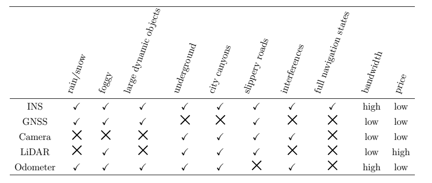
Manned or unmanned ground vehicles with autonomous ability have attracted people’s attention greatly in recent decades. These autonomous ground vehicles (AGVs) fit into two majors’ categories: unmanned ground vehicles (UGVs) and intelligent transport systems (ITSs), see for example Figure 1.1. UGVs are designed mainly to carry out missions that are not suitable for human beings, such as explorations on the moon and Mars, mine clearance, urban search and rescue (USAR), supplies delivering, improvised explosive devices localization and defusing, and so on. ITS or automated highway system research is a much broader area concerned with safer and more efficient transport in structured or urban settings. One of the current developments of ITS is driverless cars, where full autonomous driving is the ultimate goal, relieving the driver from the driving task. Ramp;D and industry activities indicate that driverless cars may hit the roads in a couple of years, with wider commercialization in 2025-2030 [2]. Now over 30 corporations are working on the self-driving cars, from traditional automobile manufacturers to leading technology companies [3]. It is predicted that growth in the fully autonomous vehicles will reach about $42 billion by 2025 and $77 billion by 2035 A number of research projects have been funded in the autonomous vehicles. The earliest competitions can date back to 2005, such as DARPA Grand Challenge (2005) and Urban Challenge (2007). Since 2009, the National Natural Science Foundation of China (NSFC) founded Intelligent Vehicle Future Challenge (IVFC) annually. One of the goals of the plan is the development of “verification platforms of unmanned vehicles with the perception of natural environment and the ability of decision-making”. Typically, the guidance, navigation, and control (GNC) system plays an essential role in providing the autonomy for AGVs. One of the key components in the GNC system is the navigation system that outputs the vehicle’s current navigation state. Enhanced performance of the navigation solution can directly lead to a better and more robust vehicle controller and path planning. Accurate vehicle navigation plays vital roles in the development of “smart cities”. Apart from the base for GNC functionalities, accurate navigation benefits the position-based services and is also used in V2X (vehicle-to-everything) technologies for effective transportation and cooperative safety communications among vehicles. For example, the positioning and heading information is shared among the V2V (vehicle-to-vehicle) network, according to the Cooperative Awareness Message (CAM) and Basic Message (BSM), from the European Telecommunications Standards Institute (ETSI) and US Society of Automotive Engineers (SAE), respectively [6, 7]. Common land navigation techniques include dead-reckoning (DR), inertial navigation, satellite navigation, local wireless positioning, landmark localization, map-matching, vision-based navigation and so on. The inertial navigation system (INS) has the sole capability to produce a complete and continuous set of navigation state data, with high precision during a short time span. However, the positioning error grows considerably with time, especially when using low-cost MEMS inertial measurement units (IMU). Therefore, INS should be integrated with other aiding sensors. INS and Global Navigation Satellite System (GNSS) integration is commonly used for outdoor vehicles navigation. Nevertheless, GNSS may not be available in tunnels and can suffer from obstruction and multipath errors in city centers and mountainous regions. There is also a possibility of a GNSS receiver being jammed or spoofed [8, 9]. Therefore, the research on various navigation techniques during GNSS outages is becoming a hot topic in
the navigation field. In the military and surveying applications, expensive high-end inertial
navigation systems are equipped in the vehicles to fulfill the precise navigation requirements,
such as in the munition launching vehicles [10] or mobile mapping vehicles [11]. With the
development of Micro-Electro-Mechanical System (MEMS) technologies, MEMS IMUs are
becoming the off-the-shelf products. Depending on the performance, the price of MEMS
IMUs ranges from several dollars to several thousand dollars. Other aiding sensors should
be incorporated with IMU sensors to mitigate the navigation error propagation during GNSS
outages. The aiding sources include wheel odometers, motion constraints, laser scanning,
images from vision sensors, traditional digital maps, and high-definition (HD) maps, which
are used for map-matching [12]. Table 1.1 lists the characteristics of different navigation or
aiding sensors and their accepted performance under different driving conditions.
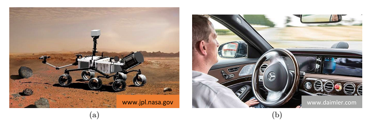
Figure 1.1: AGV examples (left: Curiosity Mars rover; right: Mercedes-Benz S 500 INTELLIGENT DRIVE)
Table 1.1
1.3 Unmanned Ground Vehicles
UGVs are vehicles that can operate without any human onboard presses. One of the reasons to introduce a UGVs is when the environment is either hazardous to humans or even impossible for humans to visits. For example, the Nasa rover Curiosity, currently exploring Mars, is a teleoperated UGV that made exploration of planetary surface possible long before we could safely send humans. Also successfully applied for automation of routine labor, UGVs has been used in the supply chain to move goods in warehouses or in agriculture as automated harvesting tractors. The flying counterpart to UGV is the UAV, see Figure 2.1 for an example. There have been two focus areas for studying autonomous driving. In the first, a car is augmented with smart systems to help a human when driving. The ambition of these system ranges from just assisted-driving to autonomous driving where the car becomes self-driving without active participation from a driver. In the second, a UGVs is equipped with systems that enable it to operate without being teleoperated by a human. Often we refer to this as self-driving when it comes to cars and autonomous when it comes to UGVs and UAVs. Autonomous UGVs have several attractive possible applications[13,14]. Firstly, they can be used as a cost-effective automation of routine labor. The warehouse robots, package delivery robots and automatic harvest tractor are examples of this. And secondly, it can extend the operation of UGVs to where no contact with humans is possible. Thick structures like caves and houses introduce communications issues. Also, when teleoperating a UGV on Mars, the great distance adds significant time delay, making driving slow. There are several potential applications for UGVs. Transportation is an interesting application. A wheel-based vehicle has in comparison to a UAV the ability to carry much heavier loads. Also, UAVs has to create lift in some way, often with either propellers or jet engines, which causes some safety concerns for operation in densely populated areas. The UGV Starship is currently being developed as an automated delivery system in urban areas, see Figure 2.1. A fleet of autonomous UGVs could also patrol a large area enabling applications in for example security and environmental monitoring or search and rescue [15,16].
1.4 Structure of UGV
The robot is mainly composed of an actuator, a driving device, a detecting device and a control system, and a complex machine. The actuator is the robot body, including the base, waist, arms, wrists, hands, and walking parts of the robot. The driving device is a structure that drives the movement of the robot. According to the control command issued by the central control system, the robot is operated by the power component. The detecting device is the current movement and operation of the detector person, and feedback is performed according to the needs of the control system. After comparing with the preset information, the control system makes a specific adjustment plan for the executing mechanism, thereby ensuring that the robot can follow the people's Willing to complete the task. Control system, its control mode has centralized control mode and distributed (level) control [17]. Centralized control, that is, complete control of the robot by a microcomputer. Decentralized (level) control, that is, using two or more microcomputers to share the control of the robot.
1.5 Key technologies of UGV
At present, the automatic navigation trolley is developing in the direction of intelligence and diversification, and has received extensive attention at home and abroad. The automatic navigation car not only has simple motion functions, but also has intelligent behaviors such as path planning, environment awareness, and logical judgment. Therefore, it is a system with a very complicated structure. The key technologies in the obstacle avoidance design of the automatic navigation trolley mainly include the following two aspects.
1.5.1 Structure and its optimization design technology
According to the needs of the actual environment, the car body structure form of the automatic navigation trolley is designed. The creative concept of the automatic navigation trolley in different fields and occasions should be combined to design a system structure that can adapt to different working environments.
1.5.2 Sensor Technology
With the rapid development of sensor technology, there are more and more types of sensor functions and better performance. A complex, powerful robot is usually equipped with temperature, vision and distance sensors. Along with the increase of sensors, the amount of information collected is also greatly increased. The information collected by each sensor is not necessarily the same in space, time, and expression, and the application range is also different, so the information processing capability is very high. Therefore, in order to coordinate the work between the sensors, the multi-sensor control system requires a comprehensive and comprehensive information processing capability [18].
1.6 The background and significance of the topic
In recent years, China's research and development of robots has achieved rich scientific and technological achievements, and some cutting-edge technologies and high-efficiency control methods have been introduced into the research and design of automatic navigation trolleys. An important branch of robotics is mobile robots. The most intelligent robots are robots that can move their logic according to environmental changes. It is an important development direction of mobile robots. It has the characteristics of individual planning and adaptability. The robot can complete the mobile tasks prescribed by people without any participation and change under the conditions of no one to participate. For example, automatic handling of goods for automated cargo delivery. Therefore, mobile robots have received extensive attention from various countries.
Chapter 2- System Description
2.1 Main Task
The main task is designing and making a vehicle with based on Ultrasonic Sensor and IR sensor which can find its way in working area (like office or lab) and also can avoid static obstacles based on its sensors. Ultrasonic sensor works for avoiding obstacle and IR sensor works for following the black line. This project is separated mainly three parts.
- Avoiding Obstacle
- Black Line Follower
- Control Robot Using Remote
2.1.1 Control System Requirements
The control system must meet the following three requirements:
- Design and plan the function block of the UGV.
- Design hardware of UGV, such as microcontroller, power supply module, ultrasonic sensors driving module, infrared sensor driving module, microcontroller is STM32F103.
- Design related software that can control the movement of the vehicle, collect vision
information, avoid the obstacles.
2.1.2 Plan Selection
Sensor Selection: The key to automatic car collection of surrounding environment information is the sensor, so the choice of sensor directly affects the judgment of the car control system. There are two main principles for selecting sensors, specially based on environmental optimization principles and task-based principles. For controlling robot with remote need keyscan Library but for avoiding obstacle no need to use remote control, that’s can run automatic after uploading Ultrasonic wave and IR library file.
The choice of the main controller: A microprocessor, a certain amount of RAM and ROM, and I/O interfaces, timers and other circuits are integrated on a single chip to form a single-chip microcomputer, referred to as a single-chip microcomputer.
The control system of the automatic obstacle avoidance car adopts STM-32F1032CT6 single-chip microcomputer as the main controller, and the structure is composed of an infrared sensor and an ultrasonic sensor, DC motor closed-loop control circuit and so on, so as to realize automatic obstacle avoidance function.
2.2 Overall System Design
Figure 2-2 Function of the system
2.2.1 Hardware Block of the system
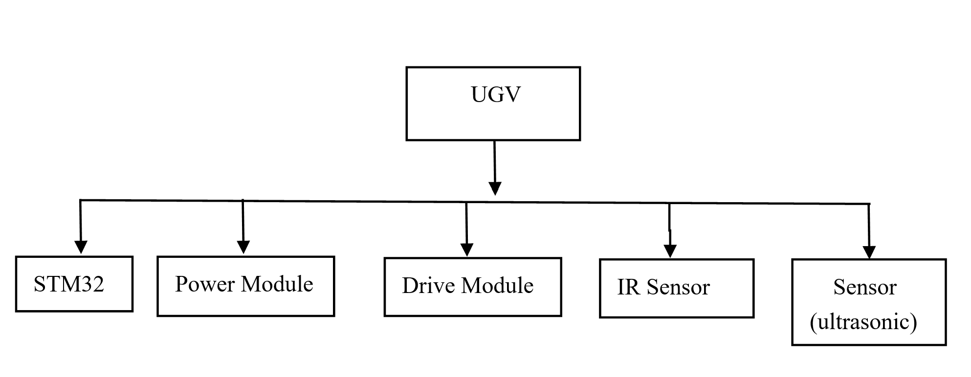
Figure 2-1-1 Hardware Block of the system
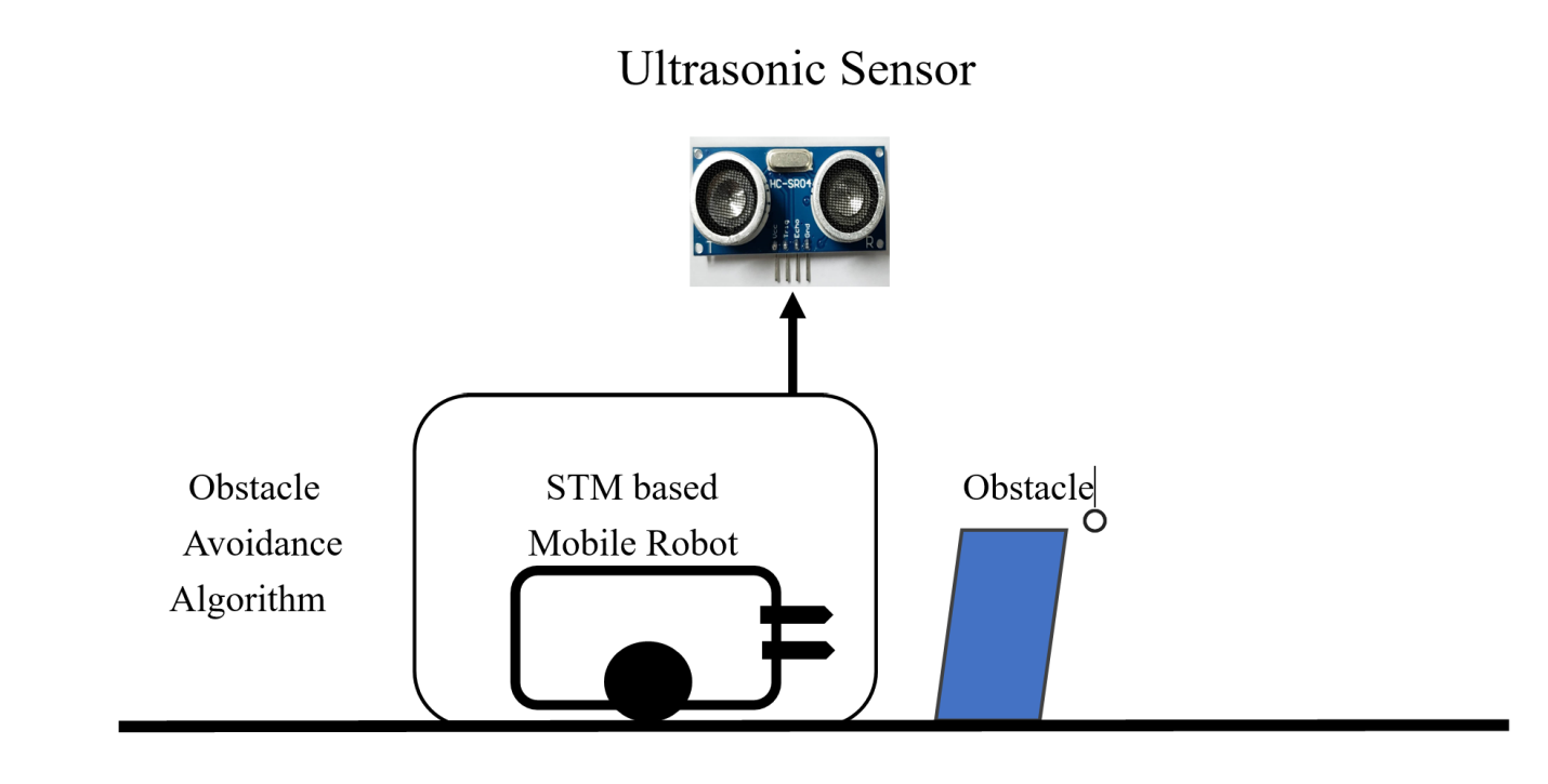
Figure 2-1 Diagram of UGV
2.2.2 System working principle
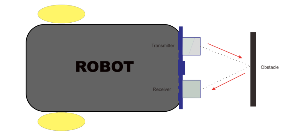 Install ultrasonic sensor sensors on the top, and also need to install IR sensor front sides of the car. When the left sensor of the car detects an obstacle, it immediately sends a signal to the Micro Controller Unit, and the Micro Controller Unit processes the received signal, then controls the DC motor, the right wheel decelerates, and the left wheel accelerates, so that the car turns to the right; Principle, when the right sensor of the car detects an obstacle, the car turns to the left; when the front or all sensors detect obstacles, the car turns backwards to avoid the bypass.
Figure 2-2 Block diagram of Robot working principle
The robot uses the Ultrasonic distance sensor to measure the distance in front of it. When this distance reduces to a particular level, the robot interprets it to mean the presence of an obstacle in its path. When the robot detects an obstacle in its path, it stops, goes backward for a few cm, looks around (right and left) then turn towards the direction that shows more free space in front of it.
Hardware components:
- 1x Arduino Uno
- 1x Robot Chassis as designed
- 1x Arduino Motor Driver L293D Model
- 1x HC-SR04 Ultrasonic Sensor
- 1x Micro Servo 9g (SG90)
- 2x DC Motor Gearbox
- 2x Wheels
- 1x Caster wheel
- 2x 3.7v Battery
- Jumper Wires
- Remote
- Switch
Chapter 3- Detailed System Design
3.1 Overview of Hardware Design
Mobile Robot consist of five major hardware’s. The main part is microcontroller that is called STM-32F103RCT6, other parts are connected with that main controller. All parts of mobile robot are listed below;
- STM-32F103RCT6
- Ultrasonic Sensor
- Power module
- IR Sensor
- Driver module
 These all major hardware parts are going to be explained.
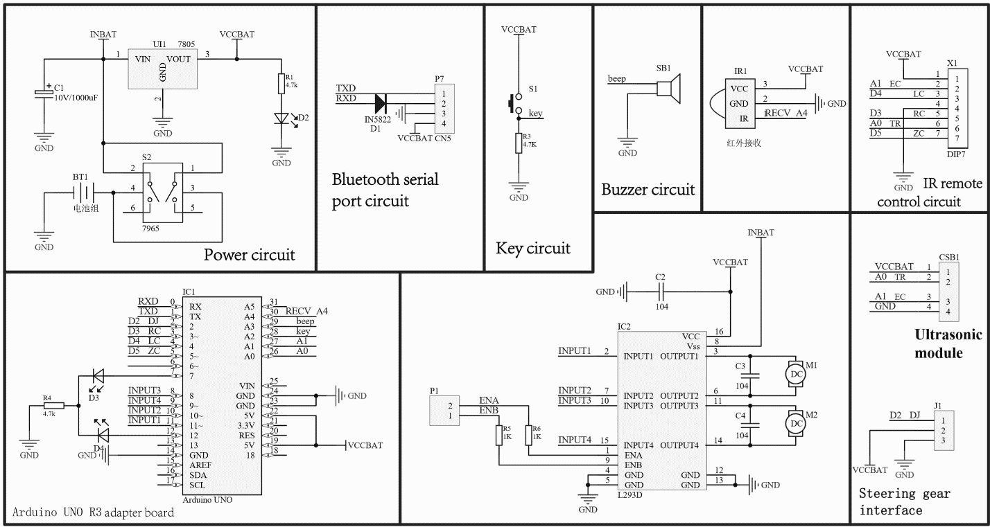
Figure 3-1 Full hardware design
3.1.1 STM-32 Microcontroller
STM32F103C Performance Series Using high-performance ARM lt; Cortex lt;-M3 32-bit RISC kernel, it runs on 72 MHz Frequency, High Speed Embedded Memory (Flash up to 512 Kbytes and SRAM as high as 64 KB, and a wide range of enhanced I/O and peripherals Connect to two APB buses. All devices provide three 12-bit ADCs, four universal 16.- Bit timer plus two PWM timers and standard and advanced communication.
Interface: Up to two I2C, three SPIs, two I2S, one SDIO, five USART, one USB and one Can. STM32F103xx High Density Performance Series Products Work from -40 to 105 degrees C Temperature range, from 2.0 to 3.6 V power supply. Comprehensive power saving Patterns allow the design of low-power applications [19]. STM32F103xx High Density Performance Series offers six different devices Packaging type: from 64 pins to 144 pins. Depending on the device selected, different settings Including peripherals, the following description outlines the full scope Peripheral equipment proposed by the family. These characteristics make STM32F103xx a high-density performance line microcontroller Series for various applications:
- Motor Drive and Application Control
- Medical and hand-held devices
- PC peripheral game and GPS platform
- Industrial applications, PLC, inverters, printers and scanners
- Alarm system, visual intercom and HVAC
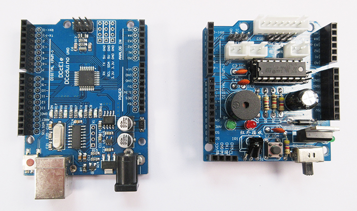
Figure 3.1.1 STM-32F103RCT6
3.1.2 Ultrasonic Sensor
Ultrasonic Ranging Module Working Principle HC-SR04 Module Detailed Explanation
 There are many types of ultrasonic ranging modules. The most commonly used URM37 ultrasonic sensors are 232 interfaces by default, which can be adjusted to TTL interface. The URM05 high-power ultrasonic sensor can test distances up to 10 meters, which is far from the test distance. In addition, there are several SRF series of ultrasonic modules that are commonly used abroad. The current ultrasonic module can reach 1cm. This article mainly explains the working principle of HC-SR04 module guitar. Firstly, it introduces the advantages and application fields of HC-SR04 module. Secondly, it explains the working principle and circuit diagram of ultrasonic ranging module. Finally, it introduces electrical parameters, ultrasonic timing diagram, operation and the program, specifically follow the small series to understand.
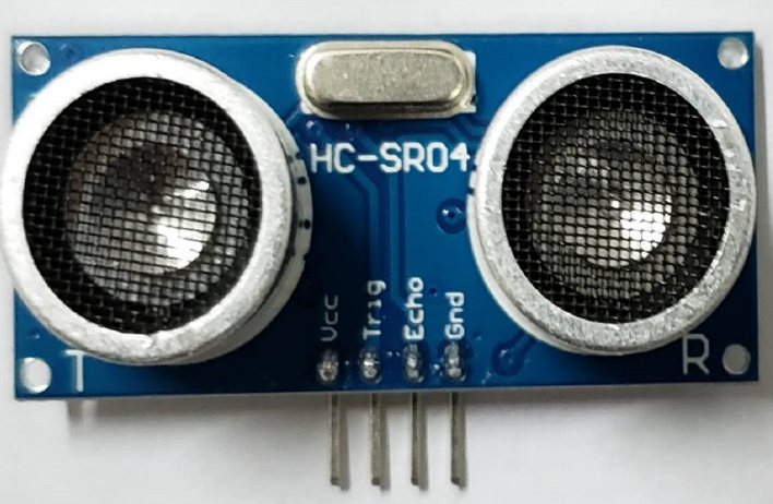
Figure 3.1.2- Ultrasonic Sensor
Advantages and application areas of the HC-SR04 module
HC-SR04 module advantage
The module has stable performance, accurate measurement distance, high precision module and small blind zone.
Product application areas:
1, Robot obstacle avoidance
2, Object ranging
3, Liquid level detection
4, Public security
5, Parking lot detection
Ultrasonic Ranging Module Works
- Using IO port TRIG to trigger ranging, giving a high-level signal of at least 10us;
- The module automatically sends eight 40khz square waves to automatically detect whether there is a signal return;
- There is a signal return, and a high level is output through the IO port ECHO, and the high-level duration is the time from the transmission to the return of the ultrasonic wave. Test distance = (high time * sound speed (340M/S)) / 2;
- This module is easy to use. A control port sends a high level above 10US, and it can wait for the high-level output at the receiving port. When there is an output, the timer can be turned on. When the port becomes low, the value of the timer can be read . At this time, the time of the ranging can be calculated. With such continuous cycle measurement, you can reach the value of your mobile measurement.
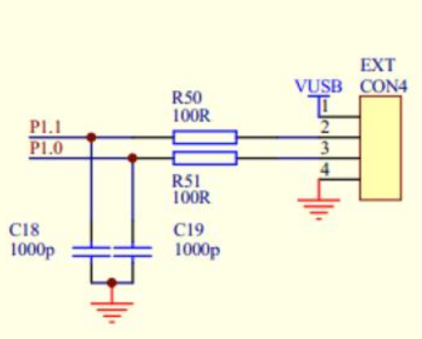
Figure- Ultrasonic ranging module circuit diagram
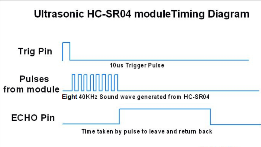 Figure- Ultrasonic timing module
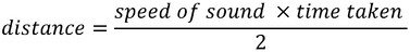 The HC-SR04 ultrasonic sensor uses sonar to determine distance to an object like bats do. It offers excellent non-contact range detection with high accuracy and stable readings in an easy-to-use package. From 2cm to 400 cm or 1” to 13 feet. Its operation is not affected by sunlight or black material like sharp rangefinders are (although acoustically soft materials like cloth can be difficult to detect). It comes complete with ultrasonic transmitter and receiver module[20]. Since it is known that sound travels through air at about 344 m/s (1129 ft/s), you can take the time for the sound wave to return and multiply it by 344 meters (or 1129 feet) to find the total round-trip distance of the sound wave. Round-trip means that the sound wave traveled 2 times the distance to the object before it was detected by the sensor; it includes the 'trip' from the sonar sensor to the object AND the 'trip' from the object to the Ultrasonic sensor (after the sound wave bounced off the object). To find the distance to the object [21] simply divide the round-trip distance in half.
HC-SR04 Ultrasonic Sensor Pin Configuration
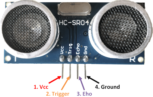
Figure 3-1 Ultrasonic Sensor Pins
Pin Number | Pin Name | Description |
1 | VCC | The VCC pin powers the sensor, typically with 5V |
2 | Trigger | Trigger pin is an Input pin. This pin has to be kept high for 10us to initialize measurement by sending US wave. |
3 | Echo | Echo pin is an Output pin. This pin goes high for a period of time which will be equal to the time taken for the US wave to return back to the sensor. |
4 | Ground | This pin is connected to the Ground of the system. |
HC-SR04 Ultrasonic Sensor – Work
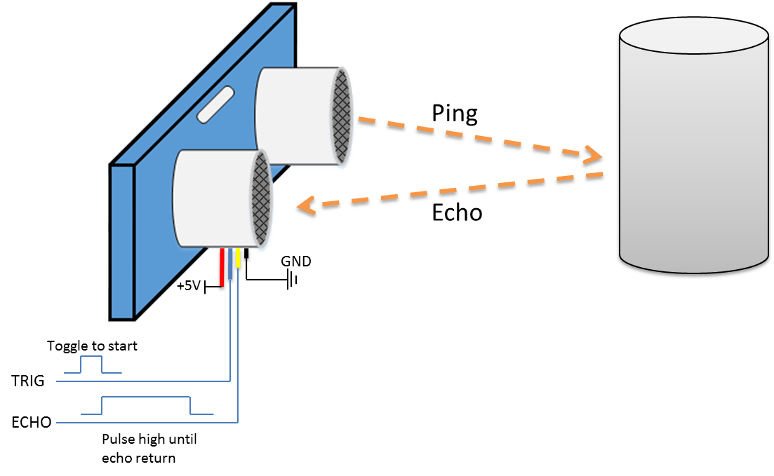
Figure- Block Diagram of Ultrasonic Sensor work
The ultrasonic sensor uses sonar to determine the distance to an object. Here’s what happens:
- the transmitter (trig pin) sends a signal: a high-frequency sound
- when the signal finds an object, it is reflected and
- the transmitter (echo pin) receives it.
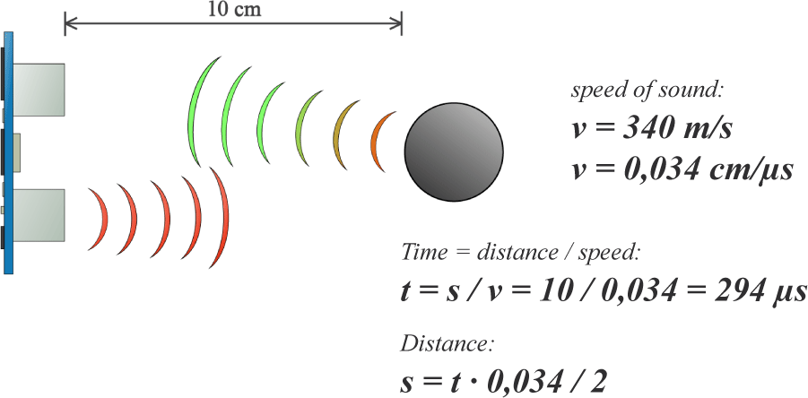
For example, if the object is 10 cm away from the sensor, and the speed of the sound is 340 m/s or 0.034 cm/µs the sound wave will need to travel about 294 u seconds. But what we will get from the Echo pin will be double that number because the sound wave needs to travel forward and bounce backward. So, in order to get the distance in cm we need to multiply the received travel time value from the echo pin by 0.034 and divide it by 2 as shown above.
HC-SR04 Ultrasonic Sensor - Applications
- Used to avoid and detect obstacles with robots like biped robot, obstacle avoider robot, path finding robot etc.
- Used to measure the distance within a wide range of 2cm to 400cm
- Can be used to map the objects surrounding the sensor by rotating it
- Depth of certain places like wells, pits etc. can be measured since the waves can penetrate through water
3.1.3 Power Supply Design
Power supply design:
(1) The operational amplifier generally uses a 7.4V DC voltage source;
(2) Digital integrated circuit devices generally use a 5V DC voltage source;
(3) The DC motor uses a 3.7V DC voltage source.
Therefore, the above uses a 7.4V DC battery as the voltage source, and the corresponding voltage source is obtained by integrating the voltage regulator. The DC voltage source obtained by the 78XX transformation has strong anti-interference characteristics. The basic circuit for voltage conversion using the 78 series integrated voltage regulator is shown in below figure-
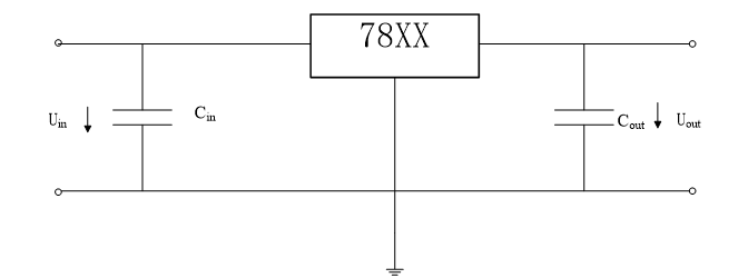
Figure 3.1.3- Basic circuit diagram of voltage conversion
The 7.4V voltage source is obtained by the 7815 regulators; the 7.4V voltage source is obtained by the 7812 regulators; the 5V voltage source is obtained by the 7805-voltage regulator.
The following three aspects should be noted when using this conversion circuit:
- Prevent self-oscillation by adding a 0.33μF capacitor Cin at the input.
- By connecting a capacitor Cout of 1μF or more at the output terminal, it is prevented that Uout has a large fluctuation due to a change in load current.
- The voltage difference between the input and output should be greater than 2V to ensure the stability of the output voltage. However, it should not be too large, otherwise it will cause the power consumption of the regulator to increase, resulting in excessive heat production. Generally, it takes 3V to 5V, and a heat sink is added.
3.1.4 Infrared Sensor
The automatic navigation trolley uses an infrared sensor: the infrared proximity switch TXO5D. Its basic parameters are:
Working voltage: 5 ~ 7.4V, the limit voltage: 12V;
Working current: 5 ~ 20mA, limiting current: 30mA;
Detection distance: 0 ~ 120cm, the detection distance is related to the working voltage, the larger the voltage, the farther the detection distance is [22].
The sensor detection distance is adjusted by adjusting the operating voltage. The design circuit diagram is shown in below figure.
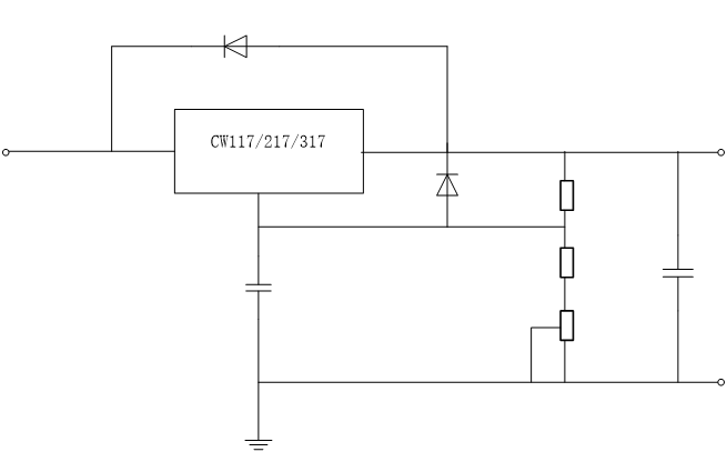
Figure 3.1.4- IR Power Supply Circuit
The CW117/217/317 series in the figure is a three-terminal adjustable positive output voltage integrated regulator with a basic output voltage of 1.25V to 12V and an output current of 1.5A. In the circuit in the figure, using a reference voltage of 1.25V, the expression of UO in the figure is:
Uo=1.25×(1 R2/R1) 50×10-6×R2
Through the above circuit design, the sensor outputs a high level when an obstacle is detected, and outputs a low level when there is no obstacle. The output high level is related to the operating voltage. Design circuit diagram to ensure that the output level is stable.
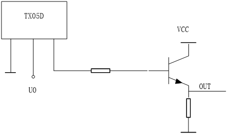
When the sensor detects an obstacle, the output is high, and the value is close to VCC. Generally, it takes 5V and vice versa. The value is close to 0V.
3.1.5 Driver Module
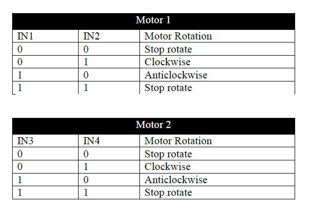 The Circuit Design of L298D Motor
The connections are pretty easy!
- Module 5V (or Vcc) - Arduino 5V pin
- Module GND - Arduino GND pin
- Module 7.4V (or Vbat) - To external power source up to 12V.
- For this tutorial just connect it with Arduino Vin pin.
- Module output 1 amp; 2 - Connect dc motor A
- Module output 3 amp; 4 - Connect dc motor B
- Module IN1 - Arduino pin 5
- Module IN2 - Arduino pin 6
- Module IN3 - Arduino pin 10
- Module IN4 - Arduino pin 9
SG-90 Servo Motor
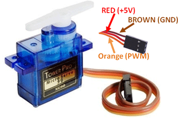
Figure 3-1-5 SG-90 Servo Motor
Servo Motors – Overview
A servo motor is an electrical device which can push or rotate an object with great precision. If we want to rotate and object at some specific angles or distance, then we use servo motor. It is just made up of simple motor which run through servo mechanism. If motor is used is DC powered then it is called DC servo motor, and if it is AC powered motor then it is called AC servo motor. We can get a very high torque servo motor in a small and light weight packages. Doe to these features they are being used in many applications like toy car, RC helicopters and planes, Robotics, Machine etc. The position of a servo motor is decided by electrical pulse and its circuitry is placed beside the motor. Now day’s servo system has huge industrial applications. Servo motor applications are also commonly seen in remote controlled toy cars for controlling direction of motion and it is also very commonly used as the motor which moves the tray of a CD or DVD player [23]. Beside these there are other hundreds of servo motor applications we see in our daily life. The main reason behind using a servo is that it provides angular precision, i.e. it will only rotate as much we want and then stop and wait for next signal to take further action. This is unlike a normal electrical motor which starts rotating as and when power is applied to it and the rotation continues until we switch off the power. We cannot control the rotational progress of electrical motor; but we can only control the speed of rotation and can turn it ON and OFF.
Servo Mechanism
It consists of three parts:
- Controlled device
- Output sensor
- Feedback system
It is a closed loop system where it uses positive feedback system to control motion and final position of the shaft. Here the device is controlled by a feedback signal generated by comparing output signal and reference input signal.
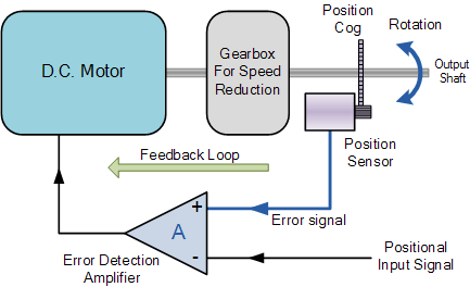
Figure 3.1.6- diagram of Servo Closed Loop System
Here reference input signal is compared to reference output signal and the third signal is produces by feedback system. And this third signal acts as input signal to control device. This signal is present as long as feedback signal is generated or there is difference between reference input signal and reference output signal. So, the main task of servomechanism is to maintain output of a system at desired value at presence of noises.
Servo Motors - Working principle
A servo consists of a Motor (DC or AC), a potentiometer, gear assembly and a controlling circuit. First of all, we use gear assembly to reduce RPM and to increase torque of motor. Say at initial position of servo motor shaft, the position of the potentiometer knob is such that there is no electrical signal generated at the output port of the potentiometer. Now an electrical signal is given to another input terminal of the error detector amplifier. Now difference between these two signals, one comes from potentiometer and another comes from other source, will be processed in feedback mechanism and output will be provided in term of error signal. This error signal acts as the input for motor and motor starts rotating. Now motor shaft is connected with potentiometer and as motor rotates so the potentiometer and it will generate a signal. So as the potentiometer’s angular position changes, its output feedback signal changes. After sometime the position of potentiometer reaches at a position that the output of potentiometer is same as external signal provided. At this condition, there will be no output signal from the amplifier to the motor input as there is no difference between external applied signal and the signal generated at potentiometer, and in this situation motor stops rotating.
Servo Motors – Controlling
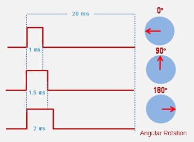
Figure 3-1-7 Position of motor shaft when PWM is generated.
Servo motor is controlled by PWM (Pulse with Modulation) which is provided by the control wires. There is a minimum pulse, a maximum pulse and a repetition rate. Servo motor can turn 90 degrees from either direction form its neutral position. The servo motor expects to see a pulse every 20 milliseconds (MS) and the length of the pulse will determine how far the motor turns. For example, as shown above Figure 3.1.7 a 1.5ms pulse will make the motor turn to the 90° position, such as if pulse is shorter than 1.5ms shaft moves to 0° and if it is longer than 1.5ms than it will turn the servo to 180°. Servo motor works on PWM (Pulse width modulation) principle[24], means its angle of rotation is controlled by the duration of applied pulse to its Control PIN. Basically, servo motor is made up of DC motor which is controlled by a variable resistor (potentiometer) and some gears. High speed force of DC motor is converted into torque by Gears. We know that WORK= FORCE X DISTANCE, in DC motor Force is less and distance (speed) is high and in Servo, force is High and distance is less. Potentiometer is connected to the output shaft of the Servo, to calculate the angle and stop the DC motor on required angle. To recap, there are two important differences between the control pulse of the servo motor versus the DC motor. First, on the servo motor, duty cycle (on-time vs. off-time) has no meaning whatsoever—all that matters are the absolute duration of the positive-going pulse, which corresponds to a commanded output position of the servo shaft. Second, the servo has its own power electronics, so very little power flows over the control signal. All power is draw from its power lead, which must be simply hooked up to a high-current source of 5 volts.
Servo Motors – Applications
- Robotics
- Animatronics
- Radio Control Cars/Boats/Planes
Servo Motors – Advantages
- Low cost - (RC Servos) Smaller sized servos can be purchased for just a few dollars.
- Variety - There is a wide range of sizes and torque ratings
- Simple to control - using logic level pulses from a microcontroller or a dedicated servo controller
DC motor
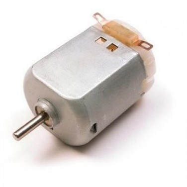
DC Motors
DC Motor – Overview
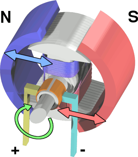
A Direct Current (DC) motor is a rotating electrical device that converts direct current, of electrical energy, into mechanical energy. An Inductor (coil) inside the DC motor produces a magnetic field that creates rotary motion as DC voltage is applied to its terminal. Inside the motor is an iron shaft, wrapped in a coil of wire. This shaft contains two fixed, North and South, magnets on both sides which causes both a repulsive and attractive force, in turn, producing torque.
DC Motor – Types
These types of motors are powered by direct current (DC).
- Brushed Motors
- Brushless Motors
- Planetary Gear Motors
- Spur Gear Motors
- Stepper Motors
- Coreless amp; Coreless Brushless Motors
- Servo Motors
- Gear heads Motors
3.2 Software Design
The controller board is used to communicate with the PC using serial communicator (USB connection). The data is transferred between them bit by bit. An adaptor is used to supply power to the controller board and a USB programmer is used to burn the hardware program (written in Arduino IDE) into the Arduino board.
 Processes and flow of program
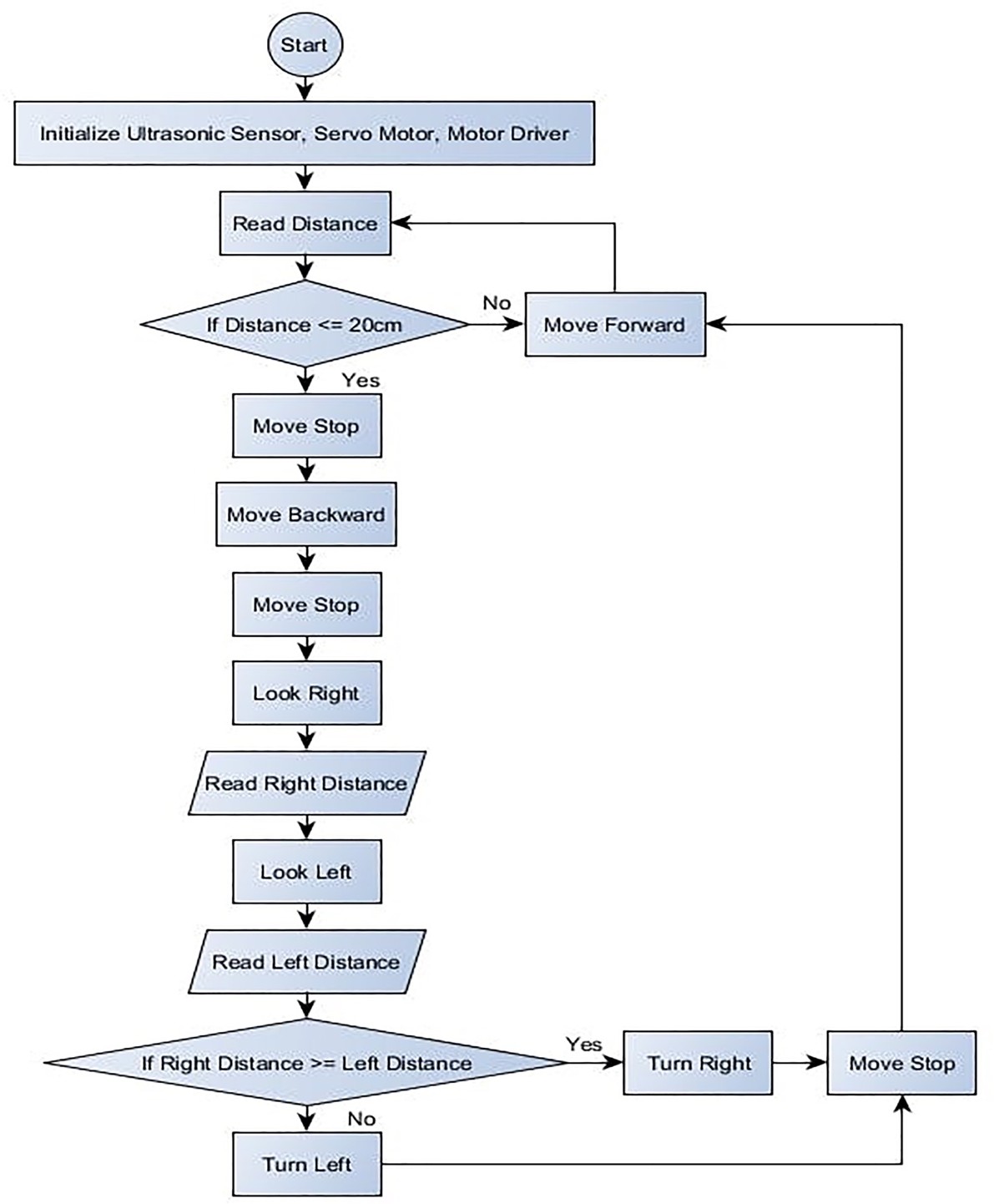
Figure 3.2 The Algorithm/ Flowchart Diagram of The Obstacle-avoiding Robot Car Based on Arduino Microcontroller
When analyzing the operating environment of the system software and clarifying the purpose of software design, the operating environment and requirements of the software are discussed, and the overall design outline of the system software is clarified. After the system is running, the software should be initialized. If the initial parameters need to be designed, the operating parameters are set; if the existing operating parameters are not set, the data is directly transferred to the motor controller. The initial value of the technology required in the PWM needs to be calculated after the motor controller receives the data, and then the counter output PWM is used to control the operation of the DC motor. The central controller 89C51 operates the infrared sensor to detect the surrounding obstacle information, confirms the obstacle information, and then makes an action command according to the previously designed algorithm, and sends the next action command to the motor controller, and the car immediately responds accordingly. Move to avoid obstacles. If a fault occurs during the operation of the system, an alarm is designed to indicate a car failure. According to the above analysis of the system software process and module, the software structure level is shown in the figure.
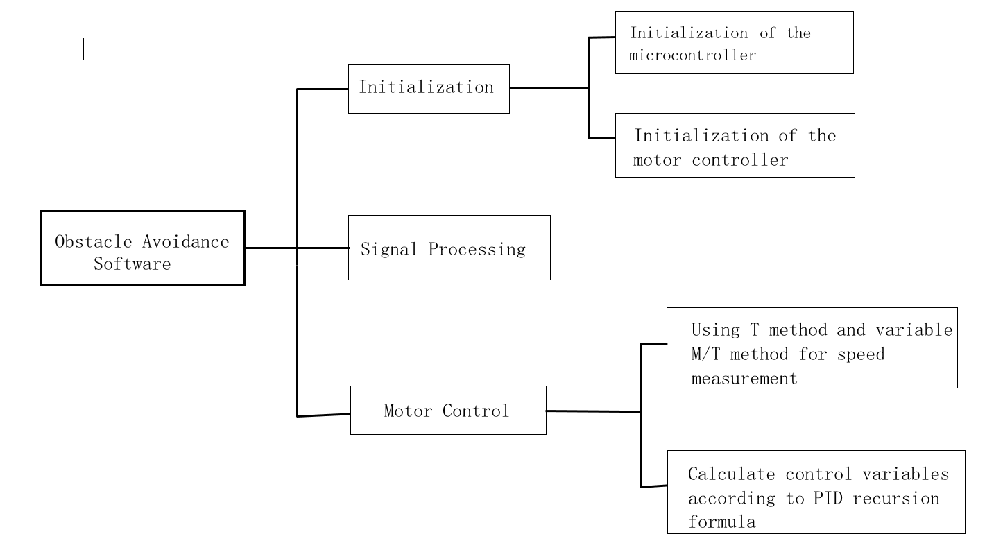
Figure 3-2 Software Design
Chapter 4- Experiment
4.1 Arduino Coding
The code uses four libraries. Two of them must be downloaded in order for the program to compile. The first one is the Ultrasonic Library for the supersonic distance sensor. The second library is the Motor Library that can control the motor speed. The third library is IR Library that can also detect the distance and can follow black line. The fourth library is keyscan library which can use to control the robot using remote. First thing we do in the code is to include the libraries that have been downloaded into the code.
- Ultrasonic Library
- Motor Library
- IR Library
- Keyscan Library
4.1.1 Ultrasonic Library
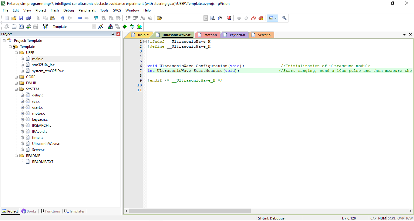
In that ultrasonic library initialize ultrasound module. Then its start ranging, send a 10us pulse and then measured the data.
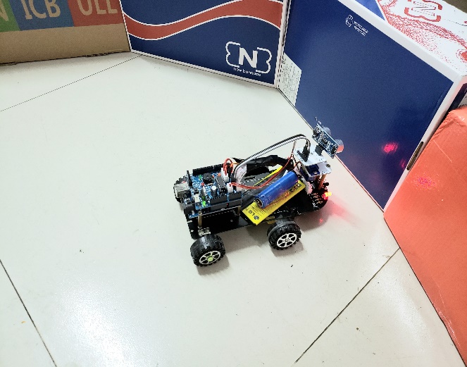
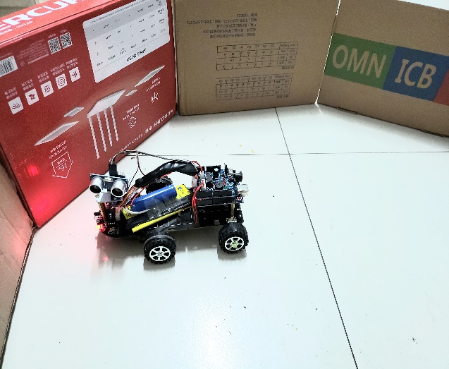
That two picture shows that mobile robot avoiding obstacle.
4.1.2 Motor Library
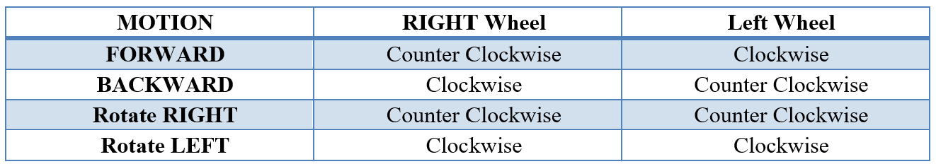
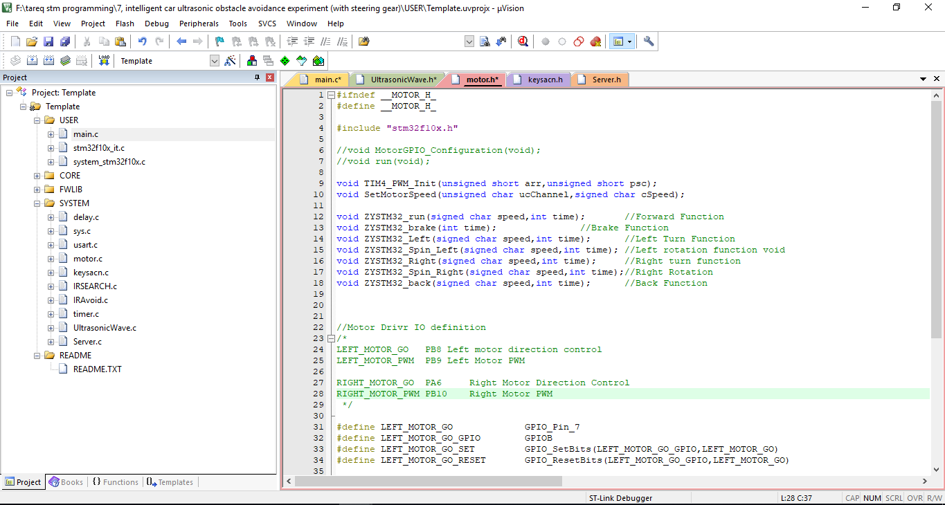
Motor library program uses to change the motion of motor. Left motor and right motor can wheel forward and backward at the same time. For this reason, right wheeler and left wheeler can move counter clockwise and also clockwise.
4.1.3 IR Library
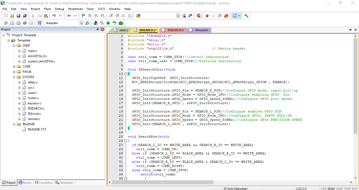
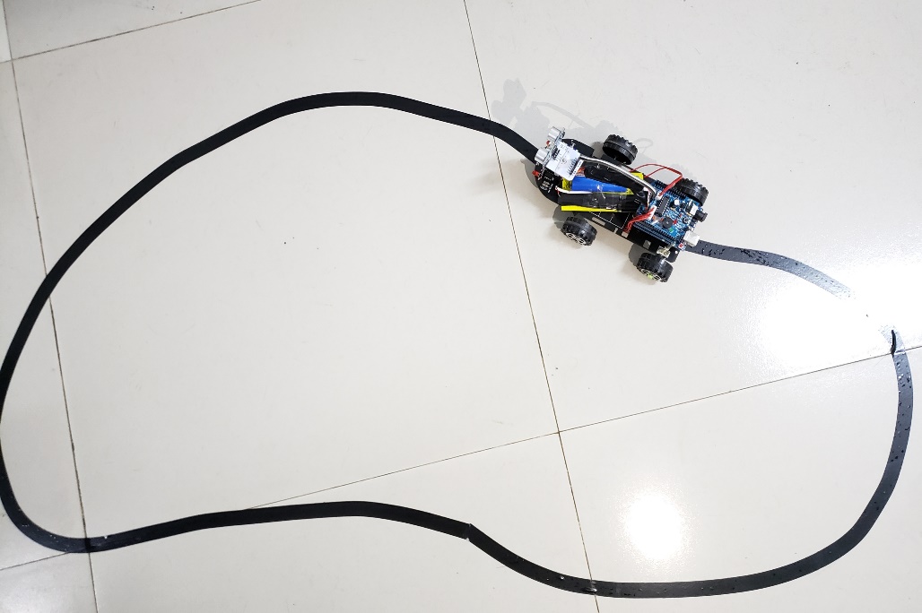 IR Library function works to detect the black line and also can detect the obstacle at the same time. But here specially it uses to detect the black line.
After debugging lR library function that mobile robot follow the black line, because that IR library function can only detect black line.
4.1.4 Keyscan library
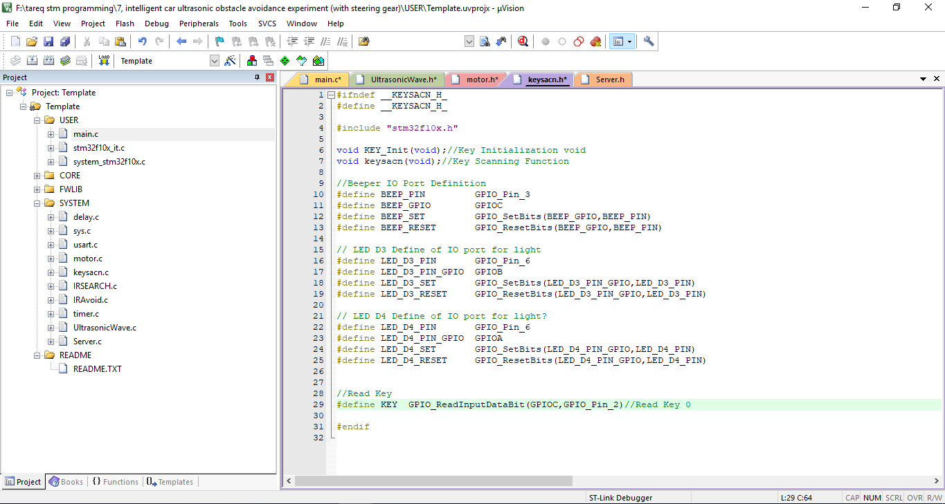

 keyscan library which can use to control the robot using remote.
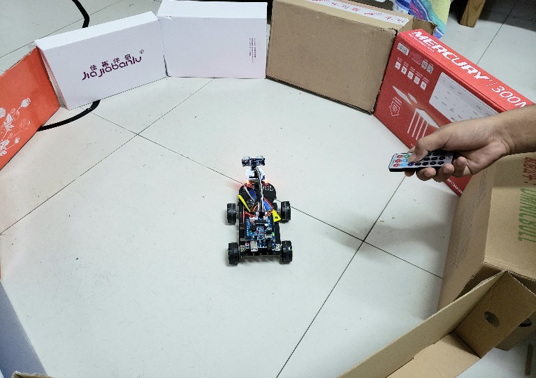
To control the robot manually need to use remote. In the remote normally are using five keys. Mobile robot will follow the left, right, forward, backward amp; stop command.
4.2 Problems Faced
Although the concept and design of the project seemed perfect, there were some problems faced while actual implementation:
The sensor cannot accurately measure distance to an object if:
- Object gt; 1 meters
- Too shallow of angle
- Object is too small
- object surface is not reflective
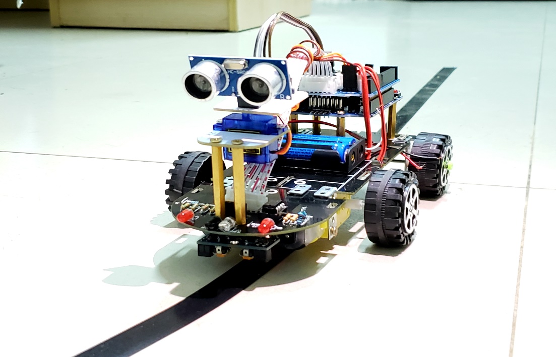
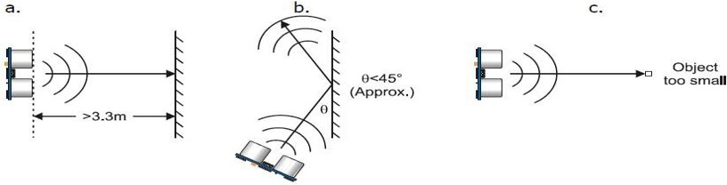
Figure 4.1.1 Ultrasonic Sensor Problems Faced
CONCLUSION
Today we are in the world of robotics. Knowingly or not, we have been using different types of robots in our daily lives. The project is "obstacle detection and avoidance robot" is demonstrated in practice by using the ultrasonic sensor to detect the robot, Motor Shield Driver for driving the DC motors, the DC motor is used for the movement of the robot with the help of Arduino Microcontroller. Many factors determined the precision of the robot we designed. These factors were the environmental phenomenon in which the robot was tested, the amount of obstacles present that make the test space crowded or relatively less crowded depending on the type and shape of the obstacle (the robot is designed for an obstacle uniform form). These factors affected mainly the sensors. The accuracy of the robot depends on the sensors used. Therefore, the nature of the sensor and its precision defined the precision of my robot.
References
[1] A. Geiger, P. Lenz, C. Stiller, and R. Urtasun, “Vision meets robotics[J]: The KITTI
dataset,” The International Journal of Robotics Research, vol. 32, no. 11, pp. 1231–
1237, 2013.
[2] “http://www.reportlinker.com/p03170270-summary/Intelligent-TransportationSystems-Driverless-Car.html.”
[3] CBINSIGHTS, “https://www.cbinsights.com/blog/autonomous-driverless-vehiclescorporations-list/,” 2016.
[4] B. C. Group, “http://www.bcg.com/en-br/expertise/industries/automotive/autonomousvehicle-adoption-study.aspx,” 2016.
[5] ResearchAndMarkets, “Global Autonomous Cars/Driverless Cars Market Analysis amp;
Trends - Industry Forecast to 2025,” tech. rep., 2016.
[6] D. Eckhoff, N. Sofra, and R. German, “A performance study of cooperative awareness
in ETSI ITS G5 and IEEE WAVE,[C]” in 2013 10th Annual Conference on Wireless
On-Demand Network Systems and Services,[M] WONS 2013, pp. 196–200, 2013.
[7] European Telecommunications Standards Institute, “Intelligent Transport Systems
(ITS) - Vehicular Communications - Basic Set of Applications - Part 2 : Specification of Cooperative Awareness Basic Service ETSI EN 302 637-2 V1.3.2,” tech. rep.,
European Telecommunications Standards Institute, 2014.
[8] J. Petit and S. E. Shladover, “Potential Cyberattacks on Automated Vehicles,”[J] IEEE
Transactions on Intelligent Transportation Systems, vol. 16, no. 2, pp. 546–556, 2015.
[9] Y. Liu, Q. Fu, Z. Liu, and S. Li, “GNSS Spoofing Detection Ability of a Loosely
Coupled INS / GNSS Integrated Navigation System for Two Integrity Monitoring
Methods,” in Proceedings of the 2017 International Technical Meeting of The Institute
of Navigation, (Monterey, California),[M] pp. 912–921, 2017.
[10] Q. Fu, Key Technologies for Vehicular Positioning and Orientation System. PhD thesis,
Northwestern Polytechnical University, 2014.
[11] N. El-Sheimy, The development of VISAT: a mobile survey system for GIS applications.[J]
University of Calgary, 1996.
177
[12] J. Levinson and S. Thrun, “Robust vehicle localization in urban environments using
probabilistic maps,”[C] pp. 4372 – 4378, 06 2010.
[13] G. Kim, J. Eom, S. Park, and Y. Park, “Occurrence and characteristics of mutual
interference between LIDAR scanners,”[J] in SPIE Optics Optoelectronics, pp. 95040K–
95040K, International Society for Optics and Photonics, 2015.
[14] G. Dissanayake, S. Sukkarieh, E. Nebot, and H. Durrant-Whyte, “The aiding of a
low-cost strapdown inertial measurement unit using vehicle model constraints for land
vehicle applications,[J]” IEEE Transactions on Robotics and Automation, vol. 17, no. 5,
pp. 731–747, 2001.
[15] X. Niu, S. Nassar, and N. El-Sheimy, “An Accurate Land-Vehicle MEMS IMU/GPS
Navigation System Using 3D Auxiliary Velocity Updates,[J]” Journal of the Institute of
Navigation, vol. 54, no. 3, pp. 177–188, 2007.
[16] J. R. Huddle, “Historical perspective on estimation techniques for position and gravity
survey with inertial systems,[J]” Journal of Guidance, Control, and Dynamics, vol. 9,
no. 3, pp. 257–267, 1986.
[17] C. Jekeli, Inertial navigation systems with geodetic applications.[J] Walter de Gruyter,
2012.
[18] E.-H. Shin, Estimation techniques for low-cost inertial navigation. PhD thesis, The
University of Calgary, 2005.
[19] G. Lachapelle, O. Mezentsev, J. Collin, and G. Macgougan, “Pedestrian and Vehicular
Navigation Under Signal Masking Using Integrated HSGPS and Self Contained Sensor Technologies,[C]” in 11th World Congress, International Association of Institutes of
Navigation, 2003.
[20] S. Godha and M. Cannon, “Gps/mems ins integrated system for navigation in urban
areas,[J]” Gps Solutions, vol. 11, no. 3, pp. 193–203, 2007.
[21] T. O. Tindall, “Evaluation of the Position and Azimuth Determining System’s Potential for Higher Accuracy Survey,” tech. rep., 1982.
[22] I. M. Rueger, W. E. Caspary, and H. Heister, “Testing a small inertial navigation
system for surveying applications,[J]” Bulletin Geodesique, no. 67, pp. 23–30, 1993.
[23] D. A. Grejner-Brzezinska, Y. Yi, and C. K. Toth, “Bridging GPS Gaps in Urban
Canyons: The Benefits of ZUPTs,[J]” Navigation, vol. 48, no. 4, pp. 217–225, 2001.
[24] P. D. Groves, “Navigation using inertial sensors,[J]” IEEE Aerospace and Electronic Systems Magazine, vol. 30, no. 2, pp. 42–69, 2015.
[25] Q. Fu, Y. Qin, and S. Li, “Zupt method for vehicular sins aided by velocity constraint,[J]”
Systems Engineering and Electronics, vol. 35, no. 8, pp. 1723–1728, 2013.
178
[26] G. Yan, Research on autonomous position and azimuth determining system of land
vehicles. PhD thesis, Xi’an: Northwestern Polytechnical University, 2006.
[27] I. Klein, S. Filin, and T. Toledo, “Pseudo-measurements as aiding to INS during GPS
outages,[J]” Navigation, Journal of the Institute of Navigation, vol. 57, no. 1, pp. 25–34,
2010.
[28] B. Aleksandr, J. F. Gardner, and P. State, “Constrained navigation algorithms for
strapdown inertial navigation systems with reduced set of sensors,[J]” in Proceedings of
the American Control Conference, (Philadelphia, Pennsylvania), pp. 1848–1852, 1998.
[29] U. Iqbal, A. F. Okou, and A. Noureldin, “An integrated reduced inertial sensor system
- RISS / GPS for land vehicle,[J]” in IEEE PLANS, Position Location and Navigation
Symposium, pp. 1014–1021, 2008.
[30] J. Georgy, A. Noureldin, M. J. Korenberg, and M. M. Bayoumi, “Low-cost threedimensional navigation solution for RISS/GPS integration using mixture particle filter,[J]” IEEE Transactions on Vehicular Technology, vol. 59, no. 2, pp. 599–615, 2010.
[31] J. Ryan and D. Bevly, “Robust ground vehicle constraints for aiding stand alone INS
and determining inertial sensor errors,[C]” in Proc. Int. Tech. Meet. Inst. Navig, pp. 374–
384, 2012.
Acknowledgments
After nearly two months, I finally finished writing this paper. I encountered numerous difficulties and obstacles in the writing process of the paper. In particular, I would like to strongly thank my teacher, Shen Jie, for his selfless guidance and help, and he have worked tirelessly to help me with the revision and improvement of the thesis. In addition, when collecting materials, our group of students also provided me with a lot of support and help. Due to my limited academic level, it is inevitable that the written papers will be inconvenient. I ask the teachers and students to criticize and correct me! I would like to express my profound gratitude to Prof. for his guidance, patience and supervision throughout my work. His stimulating ideas and suggestions help me a lot towards the development of my thesis. Thanks to the scholars involved in this paper. This article cites the research literature of several scholars. Without the help and inspiration of the research results of scholars, it will be very difficult for me. Thanks to my classmates and friends, he gave me a lot of material in the process of writing my thesis, and also provided enthusiastic help during the writing and typography of the paper. I was blessed to work among you and thanks for all your kindness and attentions.
Appendix
Programming Code
"IRAvoid.h"
#include "IRAvoid.h"
#include "delay.h"
#include "motor.h"
#include "keysacn.h"
#include "stm32f10x.h" // Device header
void IRAvoidInit(void)
{
GPIO_InitTypeDef GPIO_InitStructure;
RCC_APB2PeriphClockCmd(RCC_APB2Periph_GPIOB , ENABLE);
GPIO_InitStructure.GPIO_Pin = AVOID_PIN;
GPIO_InitStructure.GPIO_Mode = GPIO_Mode_IPU;
GPIO_InitStructure.GPIO_Speed = GPIO_Speed_50MHz;
GPIO_Init(AVOID_PIN_GPIO , amp;GPIO_InitStructure);
}
void AVoidRun(void)
{
if(AVOID_IO == BARRIER_N )
{
ZYSTM32_run(50,10);
BEEP_RESET;
LED_D3_RESET;
}
else
{
BEEP_SET;
LED_D3_SET;
ZYSTM32_brake(300);
ZYSTM32_back(50,400);
ZYSTM32_Left(50,500);
}
}
IRSEARCH.h
#include "IRSEARCH.h"
#include "delay.h"
#include "motor.h"
#include "stm32f10x.h" // Device header
char ctrl_comm = COMM_STOP;
char ctrl_comm_last = COMM_STOP;
void IRSearchInit(void)
{
GPIO_InitTypeDef GPIO_InitStructure;
RCC_APB2PeriphClockCmd(RCC_APB2Periph_GPIOA|RCC_APB2Periph_GPIOB , ENABLE);
GPIO_InitStructure.GPIO_Pin = SEARCH_R_PIN;
GPIO_InitStructure.GPIO_Mode = GPIO_Mode_IPU;
GPIO_InitStructure.GPIO_Speed = GPIO_Speed_50MHz;
GPIO_Init(SEARCH_R_GPIO , amp;GPIO_InitStructure);
GPIO_InitStructure.GPIO_Pin = SEARCH_L_PIN;
GPIO_InitStructure.GPIO_Mode = GPIO_Mode_IPU;
GPIO_InitStructure.GPIO_Speed = GPIO_Speed_50MHz;
GPIO_Init(SEARCH_L_GPIO , amp;GPIO_InitStructure);
}
void SearchRun(void)
{
if(SEARCH_L_IO == WHITE_AREA amp;amp; SEARCH_R_IO == WHITE_AREA)
ctrl_comm = COMM_UP;
else if (SEARCH_L_IO == BLACK_AREA amp;amp; SEARCH_R_IO == WHITE_AREA)
ctrl_comm = COMM_LEFT;
else if (SEARCH_R_IO == BLACK_AREA amp; SEARCH_L_IO == WHITE_AREA)
ctrl_comm = COMM_RIGHT;
else ctrl_comm = COMM_STOP;
switch(ctrl_comm)
{
case COMM_UP: ZYSTM32_run(50,10);break;
case COMM_DOWN: ZYSTM32_back(50,10);break;
case COMM_LEFT: ZYSTM32_Left(50,10);break;
case COMM_RIGHT: ZYSTM32_Right(50,10);break;
case COMM_STOP: ZYSTM32_brake(10);break;
default : break;
}
}
keysacn.h
#include "keysacn.h"
#include "delay.h"
#include "stm32f10x.h" // Device header
void KEY_Init(void)
{
GPIO_InitTypeDef GPIO_InitStructure;
RCC_APB2PeriphClockCmd(RCC_APB2Periph_GPIOA|RCC_APB2Periph_GPIOB|RCC_APB2Periph_GPIOC,ENABLE);
GPIO_InitStructure.GPIO_Pin = GPIO_Pin_2;//PC2
GPIO_InitStructure.GPIO_Mode = GPIO_Mode_IPU;
GPIO_Init(GPIOC, amp;GPIO_InitStructure);
GPIO_InitStructure.GPIO_Pin = GPIO_Pin_3;
GPIO_InitStructure.GPIO_Mode = GPIO_Mode_Out_PP;
GPIO_InitStructure.GPIO_Speed = GPIO_Speed_50MHz;
GPIO_Init(GPIOC, amp;GPIO_InitStructure);
GPIO_InitStructure.GPIO_Pin = LED_D3_PIN;
GPIO_InitStructure.GPIO_Mode = GPIO_Mode_Out_PP;
GPIO_InitStructure.GPIO_Speed = GPIO_Speed_50MHz;
GPIO_Init(LED_D3_PIN_GPIO, amp;GPIO_InitStructure);
GPIO_InitStructure.GPIO_Pin = LED_D4_PIN;
GPIO_InitStructure.GPIO_Mode = GPIO_Mode_Out_PP;
GPIO_InitStructure.GPIO_Speed = GPIO_Speed_50MHz;
GPIO_Init(LED_D4_PIN_GPIO, amp;GPIO_InitStructure);
}
void keysacn()
{
int val;
val=KEY;
while(!GPIO_ReadInputDataBit(GPIOC,GPIO_Pin_2))
{
val=KEY;
}
while(GPIO_ReadInputDataBit(GPIOC,GPIO_Pin_2))
{
delay_ms(10);
val=KEY;
if(val==1)
{
BEEP_SET;
while(!GPIO_ReadInputDataBit(GPIOC,GPIO_Pin_2))
BEEP_RESET;
}
else
}
}
motor.h
#include "motor.h"
#include "Math.h"
#include "delay.h"
#include "stm32f10x.h" // Device header
signed short sPWMR,sPWML,dPWM;
/*void MotorGPIO_Configuration(void)
{
GPIO_InitTypeDef GPIO_InitStructure;
RCC_APB2PeriphClockCmd(RCC_APB2Periph_GPIOA|RCC_APB2Periph_GPIOB, ENABLE);
GPIO_InitStructure.GPIO_Pin = LEFT_MOTOR_GO;
GPIO_InitStructure.GPIO_Speed = GPIO_Speed_50MHz;
GPIO_InitStructure.GPIO_Mode = GPIO_Mode_Out_PP;
GPIO_Init(LEFT_MOTOR_GO_GPIO, amp;GPIO_InitStructure);
GPIO_InitStructure.GPIO_Pin = LEFT_MOTOR_PWM;
GPIO_Init(LEFT_MOTOR_PWM_GPIO, amp;GPIO_InitStructure);
GPIO_InitStructure.GPIO_Pin = RIGHT_MOTOR_PWM;
GPIO_Init(RIGHT_MOTOR_PWM_GPIO, amp;GPIO_InitStructure);
GPIO_InitStructure.GPIO_Pin = RIGHT_MOTOR_GO;
GPIO_InitStructure.GPIO_Speed = GPIO_Speed_50MHz;
GPIO_InitStructure.GPIO_Mode = GPIO_Mode_Out_PP;
GPIO_Init(RIGHT_MOTOR_GPIO, amp;GPIO_InitStructure);
}
void run()
{
RIGHT_MOTOR_GO_SET;
RIGHT_MOTOR_PWM_RESET;
LEFT_MOTOR_GO_SET;
LEFT_MOTOR_PWM_RESET;
}
*/
void TIM4_PWM_Init(unsigned short arr,unsigned short psc)
{
TIM_TimeBaseInitTypeDef TIM_TimeBaseStructure;
TIM_OCInitTypeDef TIM_OCInitStructure;
GPIO_InitTypeDef GPIO_InitStructure;
RCC_APB1PeriphClockCmd(RCC_APB1Periph_TIM4, ENABLE);
RCC_APB2PeriphClockCmd(RCC_APB2Periph_GPIOA|RCC_APB2Periph_GPIOB , ENABLE);
GPIO_InitStructure.GPIO_Pin = LEFT_MOTOR_GO;
GPIO_InitStructure.GPIO_Speed = GPIO_Speed_50MHz;
GPIO_InitStructure.GPIO_Mode = GPIO_Mode_Out_PP;
GPIO_Init(LEFT_MOTOR_GO_GPIO, amp;GPIO_InitStructure);
GPIO_InitStructure.GPIO_Pin = LEFT_MOTOR_PWM;
GPIO_InitStructure.GPIO_Speed = GPIO_Speed_50MHz;
GPIO_InitStructure.GPIO_Mode = GPIO_Mode_AF_PP;
GPIO_Init(LEFT_MOTOR_PWM_GPIO, amp;GPIO_InitStructure);
GPIO_InitStructure.GPIO_Pin = RIGHT_MOTOR_GO;
GPIO_InitStructure.GPIO_Speed = GPIO_Speed_50MHz;
GPIO_InitStructure.GPIO_Mode = GPIO_Mode_Out_PP;
GPIO_Init(RIGHT_MOTOR_GPIO, amp;GPIO_InitStructure);
GPIO_InitStructure.GPIO_Pin = RIGHT_MOTOR_PWM;
GPIO_InitStructure.GPIO_Speed = GPIO_Speed_50MHz;
GPIO_InitStructure.GPIO_Mode = GPIO_Mode_AF_PP;
GPIO_Init(RIGHT_MOTOR_PWM_GPIO, amp;GPIO_InitStructure);
TIM_TimeBaseStructure.TIM_Period = arr; 80K
TIM_TimeBaseStructure.TIM_Prescaler =psc;
TIM_TimeBaseStructure.TIM_ClockDivision = 0;
TIM_TimeBaseStructure.TIM_CounterMode = TIM_CounterMode_Up;
TIM_TimeBaseInit(TIM4, amp;TIM_TimeBaseStructure);
TIM_OCInitStructure.TIM_OCMode = TIM_OCMode_PWM2;
TIM_OCInitStructure.TIM_OutputState = TIM_OutputState_Enable;
TIM_OCInitStructure.TIM_Pulse = 0;
TIM_OCInitStructure.TIM_OCPolarity = TIM_OCPolarity_High;
TIM_OC3Init(TIM4, amp;TIM_OCInitStructure);
TIM_OC4Init(TIM4, amp;TIM_OCInitStructure);
TIM_CtrlPWMOutputs(TIM4,ENABLE);
TIM_OC3PreloadConfig(TIM4, TIM_OCPreload_Enable);
TIM_OC4PreloadConfig(TIM4, TIM_OCPreload_Enable);
TIM_ARRPreloadConfig(TIM4, ENABLE);
TIM_Cmd(TIM4, ENABLE);
}
void SetMotorSpeed(unsigned char ucChannel,signed char cSpeed)
{
// static short sMotorSpeed = 0;
short sPWM;
// float fDir = 1;
if (cSpeedgt;=100) cSpeed = 100;
if (cSpeedlt;=-100) cSpeed = -100;
sPWM = 7201 - fabs(cSpeed)*72;
switch(ucChannel)
{
case 0:
TIM_SetCompare3(TIM4,sPWM);
if (cSpeedgt;0)
RIGHT_MOTOR_GO_RESET;
else if(cSpeedlt;0)
RIGHT_MOTOR_GO_SET;
break;
case 1:
TIM_SetCompare4(TIM4,sPWM);
if (cSpeedgt;0)
LEFT_MOTOR_GO_SET;
else if (cSpeedlt;0)
LEFT_MOTOR_GO_RESET;
break;
}
}
void ZYSTM32_run(signed char speed,int time)
{
signed char f_speed = - speed;
SetMotorSpeed(1,f_speed);
SetMotorSpeed(0,speed);
delay_ms(time);
}
void ZYSTM32_brake(int time)
{
SetMotorSpeed(1,0);
SetMotorSpeed(0,0);
RIGHT_MOTOR_GO_RESET;
LEFT_MOTOR_GO_RESET;
delay_ms(time);
}
void ZYSTM32_Left(signed char speed,int time)
{
SetMotorSpeed(1,0);
SetMotorSpeed(0,speed);
delay_ms(time);
}
void ZYSTM32_Spin_Left(signed char speed,int time)
{
SetMotorSpeed(1,speed);
SetMotorSpeed(0,speed);
delay_ms(time);
}
void ZYSTM32_Right(signed char speed,int time)
{
signed char f_speed = - speed;
SetMotorSpeed(1,f_speed);
SetMotorSpeed(0,0);
delay_ms(time);
}
void ZYSTM32_Spin_Right(signed char speed,int time)
{
signed char f_speed = - speed;
SetMotorSpeed(1,f_speed);
SetMotorSpeed(0,f_speed);
delay_ms(time);
}
void ZYSTM32_back(signed char speed,int time)
{
signed char u_speed = 100- speed;
signed char f_speed = - u_speed;
SetMotorSpeed(1,u_speed);
SetMotorSpeed(0,f_speed);
delay_ms(time);
}
stm32f10x.h
#include "stm32f10x.h"
#include "delay.h"
#include "motor.h"
#include "keysacn.h"
#include "IRSEARCH.h"
#include "IRAvoid.h"
int main(void)
{
delay_init();
KEY_Init();
IRSearchInit();
IRAvoidInit();
TIM4_PWM_Init(7199,0);
ZYSTM32_brake(500);
keysacn();
while(1)
{
if(AVOID_IO == BARRIER_Y )
{
BEEP_SET;
LED_D3_SET;
ZYSTM32_brake(300);
}
else
{
BEEP_RESET;
LED_D3_RESET;
SearchRun();
}
}
以上是毕业论文大纲或资料介绍,该课题完整毕业论文、开题报告、任务书、程序设计、图纸设计等资料请添加微信获取,微信号:bysjorg。
相关图片展示:


