双桨加油船动力装置设计外文翻译资料
2022-09-16 10:27:45
英语原文共 8 页,剩余内容已隐藏,支付完成后下载完整资料
|
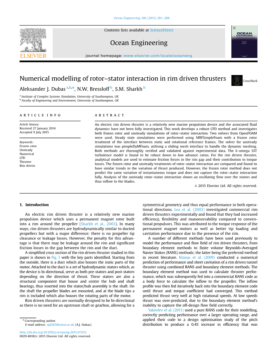
Numerical modelling of rotor–stator interaction in rim driven thrusters Aleksander J. Dubasa,b,n, N.W. Bressloffb, S.M. Sharkhb Article history: Received 27 January 2014 Accepted 9 July 2015 Keywords: Frozen rotor Unsteady Numerical CFD Thruster Rim driven Abstract An electric rim driven thruster is a relatively new marine propulsion device and the associated fluid dynamics have not been fully investigated. This work develops a robust CFD method and investigates both frozen rotor and unsteady simulations of rotor–stator interaction. Two solvers from OpenFOAM were used. Steady state simulations were performed using MRFSimpleFoam with a frozen rotor treatment of the interface between static and rotational reference frames. The solver for unsteady simulations was pimpleDyMFoam, utilising a sliding mesh interface to handle the dynamic meshing. Both methods are thoroughly verified and validated against experimental data. The k–omega SST turbulence model is found to be robust down to low advance ratios. For the rim driven thruster, analytical models are used to estimate friction forces in the rim gap and their contribution to torque losses. The frozen rotor and unsteady treatments of rotor–stator interaction are compared and found to have similar trends in the variation of thrust produced. However, the frozen rotor method does not predict the same variation of instantaneous torque and does not capture the rotor–stator interaction fully. Analysis of the unsteady rotor–stator interaction shows an oscillating flow over the stators and thus inflow to the blades. 1. Introduction An electric rim driven thruster is a relatively new marine propulsion device which uses a permanent magnet rotor built into a rim around the propeller (Sharkh et al., 2003). In many ways, rim driven thrusters are hydrodynamically similar to ducted propellers but with a major difference: there is no propeller tip clearance or leakage losses. However, the penalty for this advantage is that there may be leakage around the rim and significant friction losses in the gap between the rim and the duct. A simplified cross section of the rim driven thruster studied in this paper is shown in Fig. 1 with the key parts identified. Starting from the outside, there is a duct which also houses the static parts of the motor. Attached to the duct is a set of hydrodynamic stators which, as the device is bi-directional, serve as both pre-stators and post-stators depending on the direction of thrust. These stators are also a structural component that house and centre the hub and shaft bearings, thus inserted into the stator/hub assembly is the shaft. On the shaft the propeller blades are mounted, and at the blade tips a rim is included which also houses the rotating parts of the motor. Rim driven thrusters are normally designed to be bi-directional as there is no need for an upstream shaft or gearbox, allowing for a symmetrical geometry and thus equal performance in both operational directions. Lea et al. (2003) investigated commercial rim driven thrusters experimentally and found that they had increased efficiency, flexibility and manoeuvrability compared to conventional propulsors. This was attributed tothe torque response of the permanent magnet motors as well as better tip loading and cavitation performance due to the presence of the rim. A number of different methods have been used previously to model the performance and flow field of rim driven thrusters, from boundary element methods to finite volume Reynolds-Averaged Navier Stokes(RANS)methods; the latter being the preferred method in recent literature. Kinnas et al. (2009) conducted a numerical prediction of performance and sheet cavitation of a rim driven tunnel thruster using combined RANS and boundary element methods. The boundary element method was used to calculate thruster performance, which was subsequently fed into a commercial RANS code as a body force to calculate the inflow to the propeller. The inflow profile was then fed iteratively back into the boundary element code until thrust and torque coefficient had converged. This method predicted thrust very well at high rotational speeds. At low speeds thrust was over-predicted, due to the boundary element methods inability to capture the off-design flow field correctly. correctly. Yakovlev et al. (2011) used a pure RANS code for their modelling, correctly predicting performance over a larger operating range, and applied their code to a design optimisation study of the pitch distribution to produce a 0.4% increase in efficiency that was
subsequentlyexperimentallyverified.Additionally,theinducedstresses in the blades in various configurations were investigated and it was found that therewas a six-fold reduction of peak stress, which is another advantage of a rim drive. This allows designs to be produced with thinner, more hydrodynamically efficient, blades. Cao et al. (2012) simulated a rim driven thruster using RANS, combined with analytical models to describe the torque production of the Taylor–Couette flow in the gap between the rim and the duct. This is a large source of losses in rim driven thrusters, contributing to 27% of the total torque in the work of Cao et al. (2012), although the simulation was simplified through the use of discrete analytical models for the torque. The rim drive thruster studied by Cao et al. (2012) differs from the present one by being both hubless and statorless. In some cases stators have been shown to be beneficial to propulsive efficiency (Celik and Guner, 2007) and it may be possible to exploit the stators in a rim driven thruster. The rim driven thruster investigated in this paper utilises the stators primarily for locating the spindle and bearings, and they may be adapted to improve the hydrodynamic efficiency, but to preserve the bi-directional performance the stators must function as both pre-st 剩余内容已隐藏,支付完成后下载完整资料 资料编号:[148649],资料为PDF文档或Word文档,PDF文档可免费转换为Word |


