基于电动缸的汽车液压制动实验台架设计毕业论文
2020-02-17 10:53:20
Abstract
The hydraulic brake has been widely applied on road vehicles in recent years, and it has played a more and more significant role in the mechanical industry. It is considered as a great challenge to design a hydraulic brake system since a hydraulic brake system is composed by several components and components are supposed to have perfect corporation with each other to ensure an efficient system performance. A complete solution for designing a test bench for a brake-by-wire automotive hydraulic brake system based on electric actuator has been presented in this paper. Also the paper presents results of analytical and experimental investigations on a quantitative braking performance P-V characteristic test which is used for simulation and optimization, and the functionality of the concept is proven in an automotive hydraulic brake system. Excel is used to analysis the data and MATLAB is used to cope with the polynomial curve fitting.
Key Words:Hydraulic brake; Test bench design; Electric actuator; P-V characteristic test
Table of Contents
Abstract 0
1. Introduction 1
1.1 Background of automotive hydraulic brake system 1
1.2 Related work in China and abroad 2
1.3 Design objectives 3
2. Design of the test bench 4
2.1 General idea of the design 4
2.2 Design solutions for test bench 5
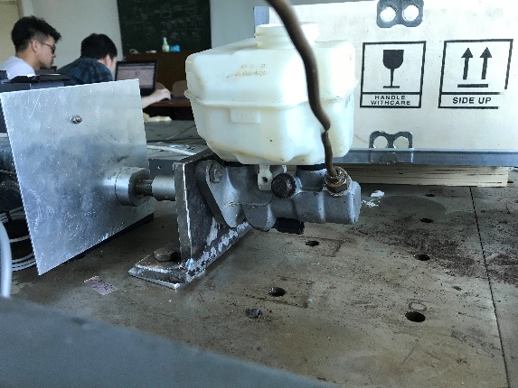
2.2.1 Design of test bench for master cylinder 5
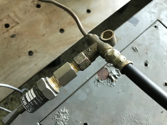
2.2.2 Design of the test bench for displacement sensor 6
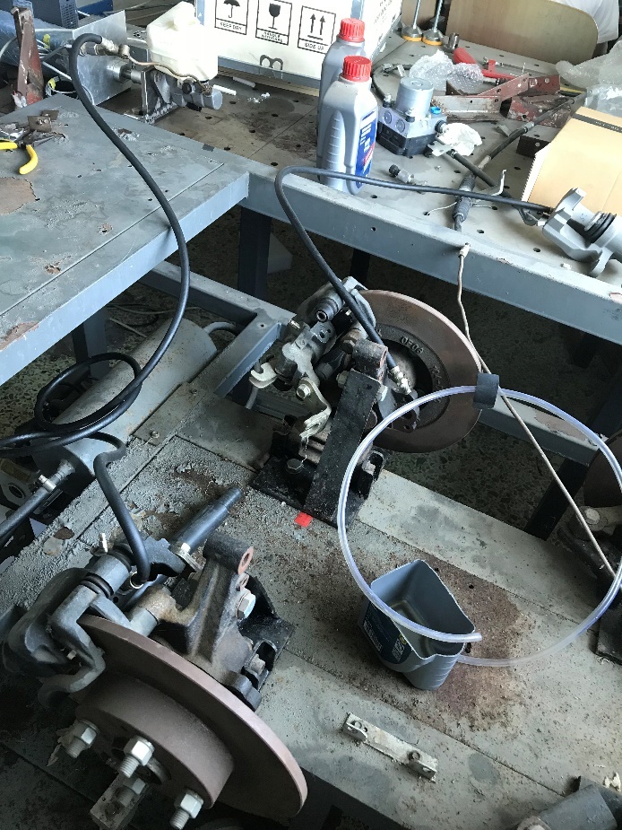
2.3 Assemble of the whole test bench 9
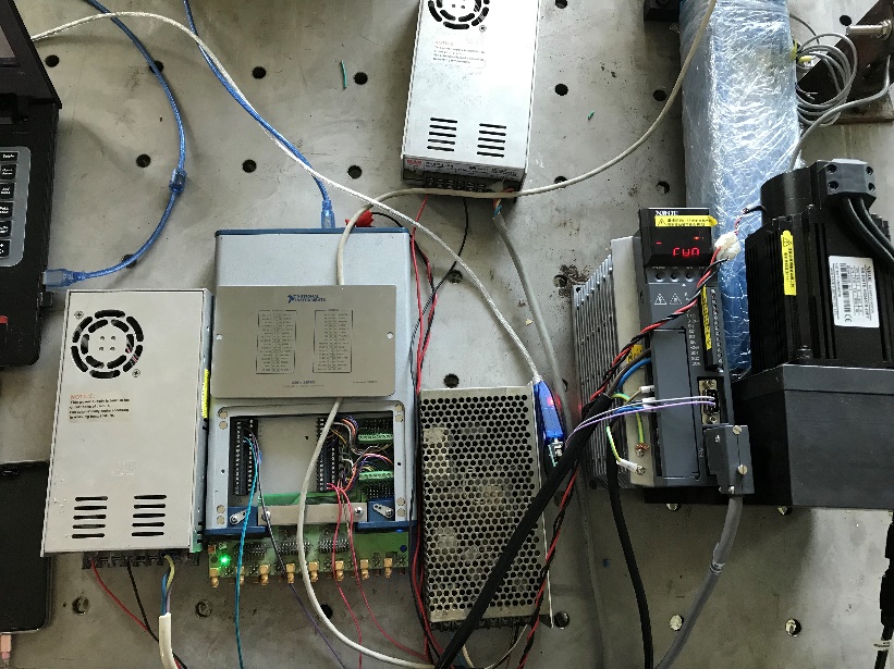
3. Control for the electric actuator 12
3.1 Introduction of electric actuator 12
3.2 Features of the electric actuator 12
3.3 Modbus protocol 13
3.4 Modbus protocol control for the electric actuator 14
4. Braking P-V characteristic test 18
4.1 Pretest process 18
4.1.1 Connecting the instruments 18
4.1.2 Pretest the sensors 18
4.1.3 Exhaust test 19
4.2 Test process 20
4.2.1 Set the “zero” point 20
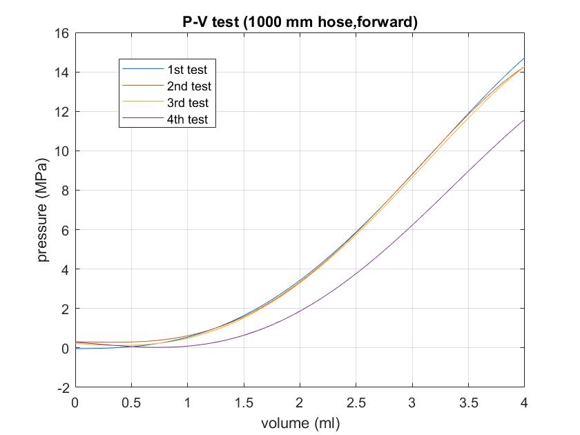
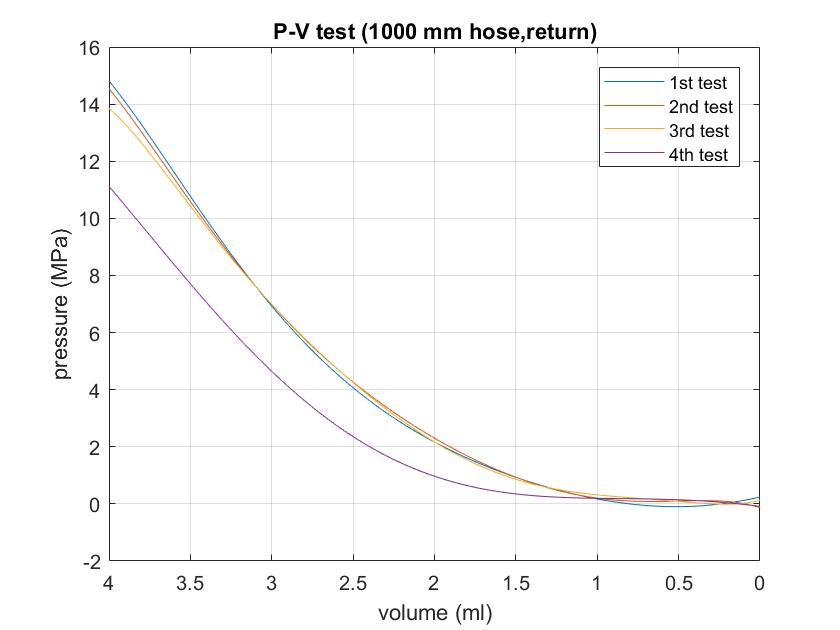
4.2.2 Recording the data (using 1000 mm hose) 21
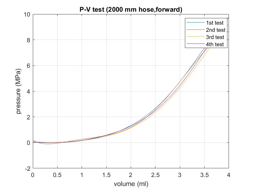
4.2.3 Recording the data (using 2000 mm hose) 22
4.3 Data processing and analysis 23
4.3.1 Recording data in Excel files 23
4.3.2 Curve fitting in MATLAB 23
4.3.3 Data analysis 25
4.4 P- T test (for minimum time to build pipeline pressure) 29
4.4.1 Test process 29
4.4.2 Data analysis 30
5. Conclusion 31
Reference 32
Appendix A P-V test MATLAB Code 34
Appendix A.1 1000 mm hose tube (forward) 34
Appendix A.2 1000 mm hose tube (return) 37
Appendix A.3 2000 mm hose tube (forward) 40
Appendix A.4 2000 mm hose tube (return) 43
Appendix A.5 Comparison between 1000 mm hose and 2000 mm hose (forward) 46
Appendix A.6 Comparison between 1000 mm hose and 2000 mm hose (return) 48
Appendix B P-T test MATLAB Code 51
Acknowledgement 53
Introduction
Background of automotive hydraulic brake system
The hydraulic brake was first invented and went on to a patent by Malcolm Lougheed in 1917, Fred Duesenberg used the Lockheed hydraulic brake on his racing cars in 1914, and Deusenberg [1] first used the hydraulic brake on a passenger car. This technology then was developed as the self-energizing hydraulic drum brake system in automotive industry and it is still widely used nowadays. The hydraulic brake has been widely applied on road vehicles in recent years, and it has played a more and more significant role in the mechanical industry. It is required continuous adjusting of the velocity of an automotive to meet the various and unpredictable traffic condition for the safe operation of an automotive. The brake system of the vehicle is a significant part to be responsible for avoiding traffic accident. To design a hydraulic brake system, there are problems arise from two main challenges which are the consideration of the number of different parts in the system and the influence of different parts on the performance of the system.
The hydraulic brake is a braking mechanism that applies different kinds of brake fluid to transfer the pressure force from controlling mechanism to the braking mechanism. The hydraulic braking system of general road vehicles is mainly composed of brake pedal, vacuum booster pump, brake master pump (also known as brake master cylinder), brake fluid (also known as brake oil), brake oil pipe, ABS pump assembly, brake sub-pump (also known as brake wheel cylinder) and wheel brake. There are three types of braking pipeline layout in the braking system which are the independent front and rear axles layout, the cross layout, and the two sets of independent layouts [2]. For the road vehicle, the cross layout is the mostly applied braking pipeline layout. In this way, when one pipeline leaks, the other pipeline still plays the role of braking, and the braking force is also relatively balanced, which can effectively avoid the deviation of braking. The brake master cylinder, brake fluid, wheel cylinder and connecting tubing are filled with brake fluid (also known as brake fluid) form a closed pressure transfer system. When the brake pedal is pressed, the piston of the master cylinder moves forward, and the pressure of brake fluid in the master cylinder increases. It enters into the sub-cylinder of each wheel through the oil pipe, and pushes the piston of the sub-cylinder to rise outside, so as to transfer the braking force from the foot to the wheel brake and push the wheel brake to brake. When the brake pedal is released, the master cylinder piston returns to its position under the action of the oil pressure and the return spring, and the piston and the wheel brake actuator of the sub-cylinder return to their position to relieve the brake on the wheels.
Related work in China and abroad
There are a huge mountain of studies and researches have been conducted on the design of the automotive hydraulic brake system. In recent years, electronic technology and integration technology have been developed notably fast, what’s more, with the combination of X-by-Wire technology [3] and vehicle braking systems, many of the vehicle sub-systems in today’s modern vehicles are being converted into “by-wire” type systems so that vehicles are becoming more and more efficient, safe and energy saving. As a consequence, there are more and more innovation and development which lead the hydraulic brake to become more electronical, thus the electronically controlled hydraulic brake (EHB) system came into being, and become a research focus and has been developed dramatically. Due to the development of vehicle electrification and intellectualization, the traditional braking system is increasingly unable to meet the needs of the vehicle control system, so the EHB system and its hydraulic pressure control method are getting more and more attention. Some foreign well-known vehicle and parts companies, such as Germany Bosch, Continental, LSP, Daimler Chrysler, the United States TRW, Delphi, Japan Hitachi, Honda, Toyota, and South Korea Mando, have proposed the electronic hydraulic braking system scheme and its hydraulic pressure control method, and they have completed some simulation and experimental research. While in China, some universities such as Tsinghua University, Jilin University, Tongji University, Nanjing university of aeronautics and astronautics, Wuhan University of Technology, Jiangsu University just started the study of electronic hydraulic brake system, most only EHB system scheme was proposed, and the EHB system hydraulic pressure control method research most remain in the simulation or test step, rarely made real vehicle tests.
The hydraulic brake is already a proven and applicable technology, and more electronic systems such as Anti-skid Brake System (ABS), Acceleration Slip Regulation (ASR), Electronic Stability Program (ESP), and Active Collision Avoidance Technology have been applied in the brake system, this makes the whole brake system more electronical. What’s more, to adapt with the dramatically growth of the social requirements for the hybrid electric vehicle, the Electronic Hydraulic brake system has been researched and applied actively on the hybrid electric vehicle [4]. Huge quantities of significant research achievement are completed by the automotive researchers. For example, Eiji Nakamura [5] has developed an EHB system named "Electronically Controlled Brake System" (ECB). The ECB integrates brake control functions such as the cooperative control between the regenerative brakes of the front or rear motors and the hydraulic brakes, ABS (Antilock Brake System), VSC (Vehicle Stability Control), TRC (Traction Control), etc. The ECB is an EHB system which has a function of controlling the hydraulic pressure of the wheel cylinder electronically. The pressure of each wheel cylinder is controlled by linear solenoid valves. As a consequence, the hydraulic pressure of wheel cylinders is controlled individually and smoothly. Seung-Jin Heo [6] has innovated and developed a Hardware-In-the-Loop Simulation (HlLS) system for EHB which includes a high pressure generator and an independent brake pressure control system. The HlLS system basically consists of three parts; the hardware, software, and interface parts. The EHB control logic has been improved in their research and was implemented on a PC. The performance of the EHB controller has been tested under various driving conditions in the HILS system, and the results are compared with those from the conventional VDC logic.
Design objectives
In this design, it is required to be familiar with the structure composition and the system operation of the hydraulic braking system of passenger cars, also be familiar with the working principle and control method of the electric actuator. More importantly, a test bench ought to be built to test the performance of the automotive hydraulic brake system which is motivated by the electric actuator. What’s more, a quantitative braking performance p-v characteristic test should be completed, in order to demonstrate the relationship between the brake pressure and the brake travel which is measured, then convert it into the relationship between the brake pressure and the required volume of brake fluid.
Design of the test bench
General idea of the design
The hydraulic brake system is mainly composed of pushrod, master cylinder, master cylinder piston, brake fluid, brake fluid reservoir, caliper, caliper piston, wheel cylinder, brake pads and brake disk, and an electric actuator is used as the controlling mechanism instead of a traditional brake pedal in this design. The pushrod exerts force on the piston in the master cylinder when the electric actuator is moving toward the master cylinder. This causes brake fluid which is stored in the brake fluid reservoir to flow into a pressure chamber. As a result, the pressure in the whole hydraulic system increases, forcing the brake fluid to caliper where it acts upon caliper pistons through the hydraulic line. Then the caliper pistons apply pushing force to the brake pads and push them against the brake disk. A braking torque is generated by the friction between the brake disk and the brake pads, and this baking torque is able to decelerate the vehicle.
以上是毕业论文大纲或资料介绍,该课题完整毕业论文、开题报告、任务书、程序设计、图纸设计等资料请添加微信获取,微信号:bysjorg。
相关图片展示: