3米盾构机主轴承试验机毕业论文
2020-06-20 19:24:11
摘 要
Abstract II
第一章 绪论 3
1.1 本课题研究的目的与意义 3
1.2 本课题在国内外的发展状况 4
1.3 本课题的主要研究内容 6
第二章 设计方案提出对比与成本预算 7
2.1 不同方案的构想 7
2.1.1 工作油压的采用 7
2.1.2 加载板形状的选择 7
2.1.3 轴承与轴承之间,轴承与试验台之间的连接方案 8
2.2 成本预算 8
第三章 计算 10
3.1 液压泵的计算及选型 10
3.1.1 系统工作压力的确定 10
3.1.2 确定被试件的载荷 10
3.1.3 初步确定液压缸布置方案 10
3.1.4 初选缸径D,杆径d 11
3.1.5 实际载荷计算 12
3.1.6 液压缸最终内径与数量的校核 12
3.1.7 实际选型 12
3.1.8 确定最终布置方案 13
3.2 驱动方案设计 13
3.2.1 摩擦阻力矩计算 13
3.2.2 与内齿啮合的小齿轮参数 13
3.2.3 液压柱塞马达选型 14
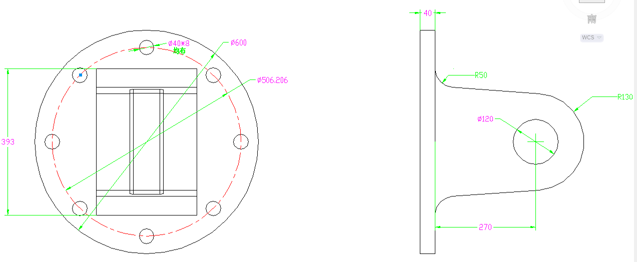
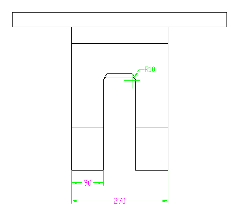
3.3 螺栓盘的设计 14
3.3.1 螺栓盘的作用 15
3.3.2 螺栓盘的要求 15
3.3.3 螺栓盘的设计 15
3.3.4 螺栓盘的材料 16
力学性能如下: 16
3.4 转接板和连接盘的设计 17
3.4.1 部件的作用 17
3.4.2 部件的要求 17
3.4.3 设计部件 17
3.4.4 部件的材料 19
3.5 底座的设计 20
3.5.1 底座的作用 20
3.5.2 底座的要求 20
3.5.3 设计底座 20
3.5.4 底座的材料 21
3.6 螺栓的校核 21
3.6.1 固定轴向液压缸的螺栓 21
3.6.2 与提供径向力的液压缸连接的螺栓盘的螺钉校核 23
3.6.3 转接板和转接盘上的螺钉校核 24
3.7 加载板的设计 26
3.7.1 加载板的作用 26
3.7.2 加载板的要求 26
3.7.3 加载板设计 26
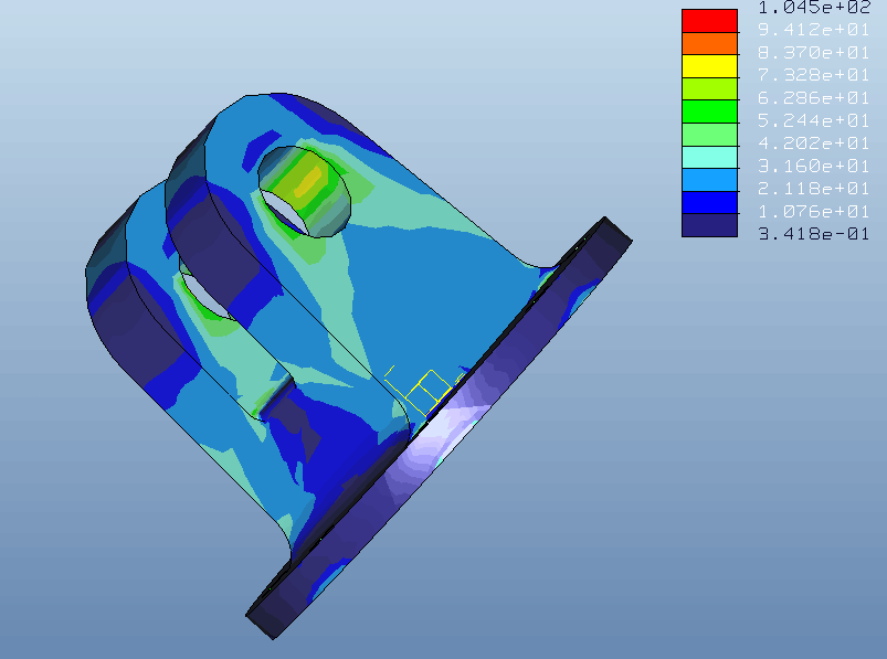
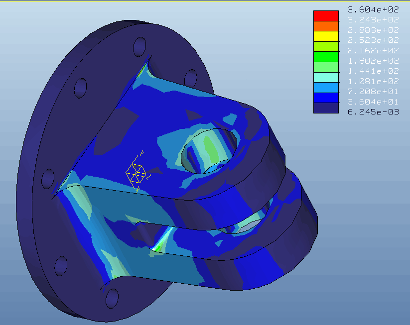
3.8 主支架的设计 27
3.8.1 主支架的作用 27
3.8.2 主支架的要求 27
3.8.3 主支架的设计 27
3.9 总装配方案 29
最后将设计的各部件装配,三视图如下: 29
第四章 总结与感悟 31
参考文献 32
致谢 34
摘要
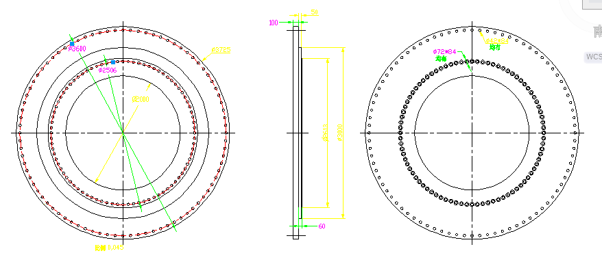
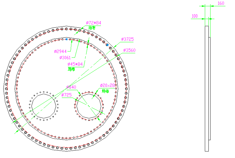
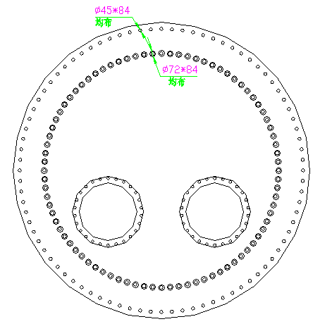
作为盾构掘进机重要部件的主轴承多采用三排柱回转支承结构,其复杂的实际工况和缺少设计生产检验方法等方面对试验台的开发提出了迫切要求。本文设计的试验机能够模拟盾构机主轴承在实际工作中受到的力,包括轴向力、径向力和倾覆力。通过对其加载系统及液压系统的调整,能够分别控制受到的不同种类的力的大小,从而能够使试验台对主轴承的加载力更贴近现实。为了精准检测被测试的主轴承是否满足指标要求,需要在测试时采集数据并进行处理。
本试验台的设计过程:首先,先根据要求确定了试验台的总体加载和驱动方案,然后对主要部件进行具体设计,并对主要受力部件进行校核计算。机械结构设计包括三个部分:加载系统,装夹机构和传动系统的机械结构。其中,加载系统即为液压系统的设计,采用31.5Mpa压力的工作压力。装夹机构为液压油缸的选型和位置的布置,这一部分是本设计的重点内容,通过对油缸选型方案的优化和布置方案的改进,能适当减小试验台的体积并且缩减成本。传动系统的机械结构形式包括液压马达的选型和减速装置的选型。
关键词:主轴承 盾构机 试验机 测试 装夹机构
Abstract
The main bearing of the shield machine adopts the rotary support structure,The test machine can simulate the shield machine main bearing in the actual work by the force, including axial force, radial force and overturning force. By adjusting the loading system and the hydraulic system, it is possible to control the size of the different kinds of forces received separately, so that the loading force of the test bed can be made closer to reality. So that it is possible to accurately monitor whether the rotating support structure of the tested main bearing can achieve the desired performance.
The design of the test bench consists of three parts: the mechanical structure of the loading system, the clamping mechanism and the transmission system. Among them, the loading system is the hydraulic system design, the use of 31.5Mpa pressure working pressure. The clamping mechanism is the layout of the hydraulic cylinder and the layout of the position. This part is the key content of this design. By optimizing the cylinder selection scheme and improving the arrangement, the volume of the test bed can be reduced and the cost can be reduced. The mechanical structure of the transmission system includes the selection of the hydraulic motor and the selection of the reduction gear.
Key Words:main bearing; shield machine; testing Machine; test;clamping mechanism
绪论
相关图片展示: