机械整流馈能减振器设计毕业论文
2020-02-17 17:47:51
摘 要
汽车在行驶过程中耗散在悬架部分的振动能量大约占汽车发动机输出总能量的16%-18%,具有很大的能量回收潜力和价值;传统减振器通过将悬架往复振动的机械能转换成热能的形式耗散掉,如果将这部分能量加以回收利用,在提升汽车的燃油经济性的同时,在通过相应控制方法加以控制根据不同路面激振力改变减振器的阻尼力,还能够提升车辆的操纵稳定性和乘坐的舒适性。近年来各地的学者关于馈能式减振器开展了不同的研究,设计了不同结构和原理的馈能式减振器。
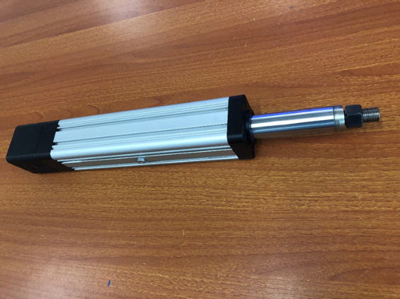
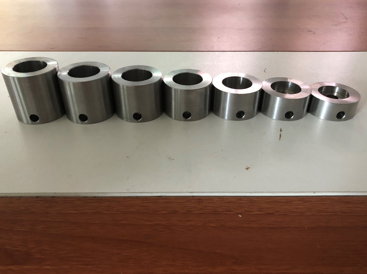
本文提出了一种新型的机械整流馈能减振器的设计方案,并试制了试验样机;该试验样机匹配了不同大小的转动惯量,可以研究转动惯量对能量回收效率的影响;匹配了不同传动比的压缩行程和伸张行程齿轮对,在压缩行程和伸张行程产生不同的阻尼力;具有扭转减振单元,减少机械传动结构的磨损增加了装置寿命,依托的项目是国家自然科学基金面上项目“并联互通液电馈能式主动径向转向架理论及试验研究”。具体的工作如下:
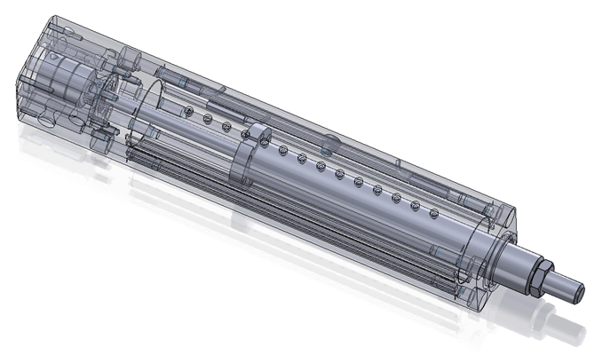
(1)完成了该机械整流馈能减振器总体布置设计,完成了滚珠丝杆副、电机、惯量、整流齿轮箱以及扭转减振单元的设计和选型,并在Solidworks中建立了三维模型;
(2)在Ansys的workbench模块中对此机械整流馈能减振器重要传动零件,如齿轮对、传动轴以及整流齿轮箱壳体进行了有限元分析校核;
(3)通过理论计算,将此机械整流馈能减振器等效为固定惯容器和由发电机负载电阻调节的阻尼器并联的动力学模型,在Matlab中绘制了该减振器的阻尼力F-车身位移Z曲线;
(4)搭建了试验台架,完成了台架试验,验证了此机械整流馈能减振器的技术可行性和设计方案的可靠性;通过使用扭转减振单元和不使用扭转减振单元试验的对比,验证加装此扭转减振单元对此减振器的机械承载性有提升;通过更换不同的转动惯量,测试并具体分析,转动惯量对此机械式馈能减振器能量回收效率的影响;通过更换不同的伸张行程齿轮对,改变其传动比,测试并分析压缩和伸张行程不同传动比对能量回收效率的影响。
关键词:馈能;减振器;单向离合器;机械整流;扭转减振;Solidworks;滚珠丝杆;Ansys
Abstract
The vibration energy dissipated in the suspension during driving accounts for about 16%-18% of the total energy output of the automobile engine, which has great potential and value of energy recovery. Traditional shock absorber by suspension reciprocating vibration of mechanical energy is converted into heat energy in the form of wasted, if this part of the energy would be recycled, not only can improve the fuel economy of vehicles, if controlled through corresponding control methods according to different road surface vibration force change shock absorber damping force, but also can improve the vehicle handling stability and ride comfort. In recent years, scholars all over the world have carried out different studies on energy-regenerative shock absorber and designed different structures and principles of energy-regenerative shock absorber.
In this paper, a new type of mechanical rectifier energy-regenerative shock absorber is designed and a prototype is developed. The experimental prototype is matched with different rotary inertia, and the influence of rotary inertia on energy recovery efficiency can be studied. The compression stroke and stretching stroke gear pairs with different transmission ratios produce different damping forces in the compression stroke and stretching stroke. With the torsion damping unit to reduce the wear of mechanical transmission structure and increase the service life of the device, the project supported by the national natural science foundation of China is "the theoretical and experimental research on parallel interconnected hydro-electric fed type active radial bogie". The specific work is as follows:
(1) Completed the overall layout design of the mechanical rectifier energy-regenerative shock absorber, completed the design and model selection of the ball screw pair, motor, inertia, rectifier gear box and torsion damping unit, and established the three-dimensional model in Solidworks;
(2) In the Ansys workbench module, finite element analysis and verification are carried out for the important transmission parts of the mechanical rectifier energy-regenerative shock absorber, such as gear pairs, transmission shafts and the shell of the rectifier gear box;
(3) Through theoretical calculation, the mechanical rectifier energy-regenerative shock absorber is equivalent to the dynamic model of the parallel connection between the fixed inertial container and the damper regulated by the load resistance of the generator. The damping force f-body displacement Z curve of the damper is drawn in Matlab.
(4) The test bench is set up and the test is completed, which verifies the technical feasibility and reliability of the design scheme of the mechanical rectifier energy-regenerative shock absorber; By comparing the test of using torsional damping unit with that of not using torsional damping unit, it is verified that the mechanical bearing capacity of the shock absorber is improved by adding the torsional damping unit. The influence of the moment of inertia on the energy recovery efficiency of the mechanical energy-regenerative shock absorber is tested and analyzed. The energy recovery efficiency is tested and analyzed by changing the transmission ratio of different stretching gear pairs.
Key Words:Energy-regenerative;Shock absorber;One-way clutch;Mechanical rectifier;Torsion damper;Solidworks;Ball screw;Ansys
目录
摘 要 I
第1章 绪论 3
1.1 研究背景 3
1.2 研究概况 4
1.2.1悬架中的能量回收潜力 4
1.2.2馈能式减振器的研究现状 4
1.3本文设计的内容 7
第2章 机械整流馈能减振器的设计 9
2.1机械整流馈能减振器总体设计 9
2.2滚珠丝杆设计 9
2.2.1滚珠丝杆参数选择 9
2.2.2滚珠丝杆设计的校核 10
2.2.3滚珠丝杆壳体设计及模型绘制 11
2.3电机选型及惯量设计 12
2.4整流齿轮箱设计 13
2.4.1整流齿轮箱传动齿轮设计 13
2.4.2传动轴设计 15
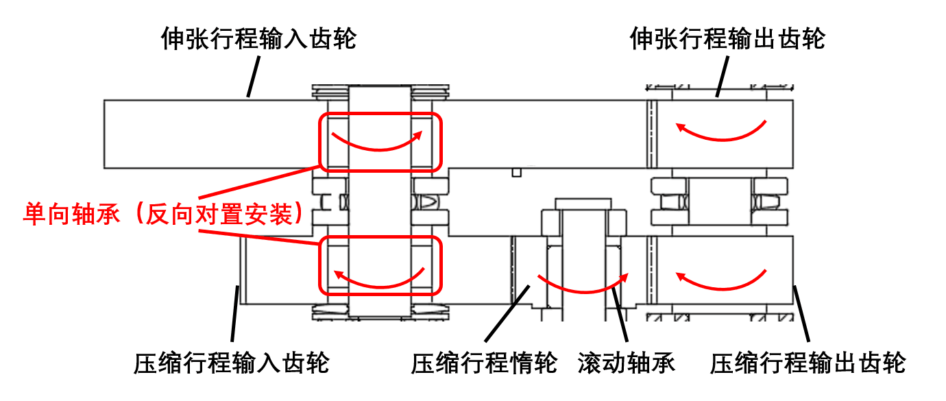
2.4.3单向离合器选择 17
2.4.4整流齿轮箱壳体设计及整流齿轮箱模型绘制 18
2.5扭转减振单元选择 19
2.6机械整流馈能减振器工作原理 19
2.7本章小结 20
第3章 关键零部件校核 21
3.1齿轮对校核 21
3.2传动轴的校核 23
3.3整流齿轮箱壳体的校核 25
第4章 机械式馈能减振器的动力学模型 27
第5章 机械式馈能减振器台架试验 30
5.1台架试验的目的 30
5.2试验方案 30
5.3台架试验结果分析 31
5.3.1发电结果分析 31
5.3.2阻尼力和位移结果分析 33
5.4试验小结 35
第6章 总结与展望 36
6.1全文总结 36
6.2本文创新点 36
6.3研究展望 37
参考文献 38
致 谢 40
附件1 MATLAB程序 41
第1章 绪论
1.1 研究背景
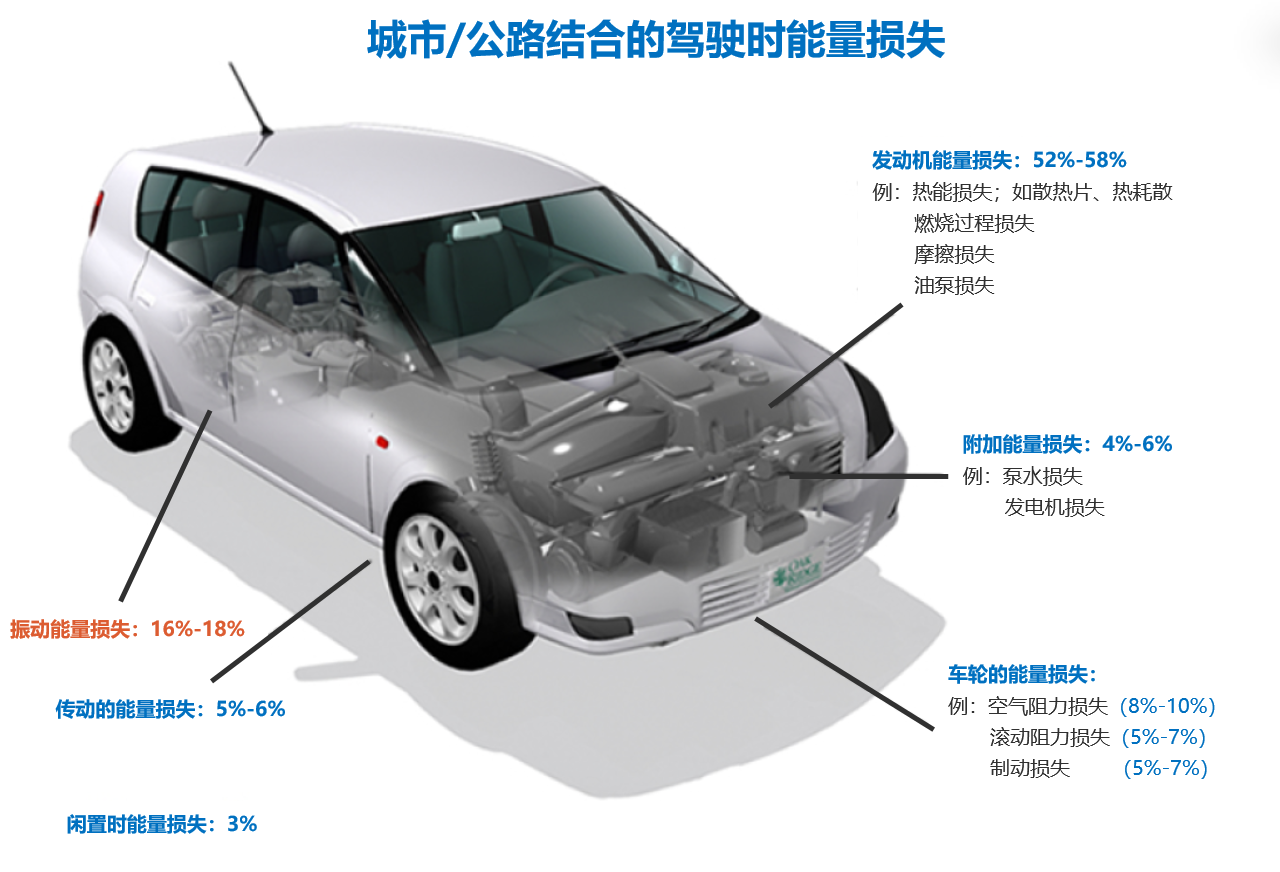 汽车产业是我国的支柱型产业之一,在“工业4.0战略”以及“中国制造2025”的大背景下,我国汽车行业正朝着“轻量化”、“智能化”、“网联化”、“电动化”的大方向迅速发展[1]。我国在发展新能源汽车技术上投入了大量人力物力资源,同样取得了丰硕的成果。但是在目前的电池技术的限制下,纯电动车的连续行驶里程仍难以满足用户的需求[2]。但是电池技术在近几年的研究中也未取得革命性的突破,因此成为了新能源汽车发展过程中的瓶颈[3]。在此背景下,探索汽车能源新的补给方案,丰富汽车能源构成,对推动新能源汽车技术的发展具有重要意义。根据美国能源部数据统计,如图1.1所示,在汽车的正常行驶过程中,只有大约10-16%的燃油能量用于车辆的行驶驱动,其中大部分的能量损耗在于发动机的热效率较低,而汽车在行驶过程中消耗在悬架部分的振动能量约占汽车发动机输出总能量的16%-18%[4],传统减振器通过将悬架振动的机械能转换成热能的形式耗散掉,若将这部分能量加以回收,不仅可以改善汽车的燃油经济性,如果通过相应控制方法加以控制根据不同路面激振力改变减振器的阻尼力,还能够提升车辆的操纵稳定性和乘坐的舒适性[5]。因此,近年来馈能式减振器受到了大量学者的关注。
图 1.1 汽车行驶时能量损失
1.2 研究概况
1.2.1悬架中的能量回收潜力
悬架系统的能量回收潜力受路面不平度系数、行驶速度、轮胎刚度等因素的影响[6]。各个学者,对于不同条件下的汽车悬架系统的能量回收潜能也有过估算,弗吉尼亚理工大学左磊教授曾通过仿真得出过,一辆中型轿车在C级路面上以左右的速度行驶时,悬架耗散的能量可以达到400W [7]。吉林大学的Yu等人也分析了馈能式减振器的能量回收潜力,通过理论仿真得出中型车辆在C级路面上以72km/h的速度行驶20s,通过减振器转化为热能耗散掉的能量可达650KJ左右[8]。德国奥迪汽车公司也在不同路面上测试了普通轿车行驶时悬架系统的能量回收潜力,在德国普通路面上行驶时,悬架耗散的能量为150W,而当轿车在德国的颠簸不平的路面上行驶时,悬架耗散的能量可达610W左右。
1.2.2馈能式减振器的研究现状
通过上述文献,不难发现悬架系统具有巨大的能量回收潜力,为了验证悬架系统中存在的能量,各国的学者研制了形式原理不同的馈能式减振器,按照减振器的能量转换路线的不同,所有馈能式减振器目前大致可以分为直线-电机式、机械-旋转电机式和液压-旋转电机式三大类。
- 直线电机式馈能减振器
 直线电机式的馈能减振器,主要是采用直线电机来发电的原理,通过磁铁和线圈之间的线性运动将悬架中垂直方向上的振动能量直接转化为电能。
图 1.2 Bose公司采用直线电机的馈能悬架
2003年,日本山口大学的Nakano等人提出了一个可以自供电的隔振控制系统,将直线电机安装在悬架上可以实现主动减少振动的功能并有馈能调节的系统,其原理是将电机高速运动时产生的能量储存起来,在振动能量较少时用来驱动电机,而当回收的能量大于驱动所需的能量时,还可以通过自供电主动控制系统来使用回收的能量[9]。
2004年,Bose公司就提出过可以用直线电机代替弹簧和减振器的功能,悬架系统的垂直方向上的往复振动使直线电机产生不同的伸张和收缩,通过电磁阻力来抵消道路的冲击载荷并且能回收部分能量,其结构如图1.2所示。
2010年,美国弗吉尼亚理工大学的左磊等人,对直线-电机式馈能减振器进行了一次详细的研究,采用了稀土永磁体和高磁导率的滑环构成了一种新型的直线电机,从而设计了一种结构紧凑的馈能式减振器,试验中该样机的能量回收效率可达到70%-80%,但是也发现其最大阻尼较低[10]。
以上是毕业论文大纲或资料介绍,该课题完整毕业论文、开题报告、任务书、程序设计、图纸设计等资料请添加微信获取,微信号:bysjorg。
相关图片展示:
![C:\Users\admin\Documents\Tencent Files\562043890\FileRecv\MobileFile\Image\Z}3_[BPULK5]A}@X1$Z[CUG.png](http://www.biyelunwen.org/wp-content/uploads/2020/02/lw7813_2020217174740461.png)