混凝土的结构使用。第1部分:设计和施工的实施规程 第四节。设计与详图:预应力混凝土外文翻译资料
2023-06-25 10:00:36
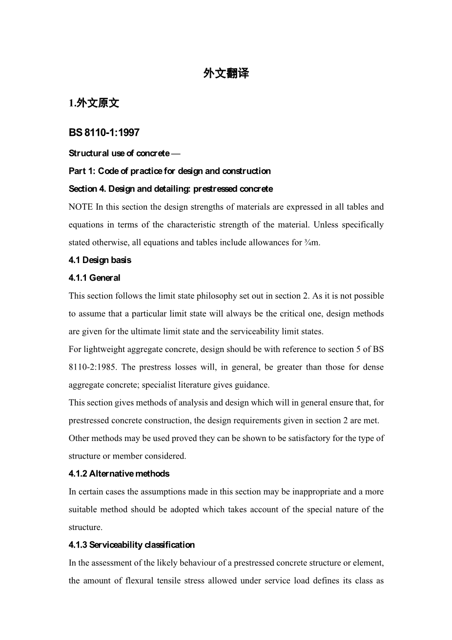
BS 8110-1:1997
Structural use of concrete —
Part 1: Code of practice for design and construction
Section 4. Design and detailing: prestressed concrete
NOTE In this section the design strengths of materials are expressed in all tables and equations in terms of the characteristic strength of the material. Unless specifically stated otherwise, all equations and tables include allowances for frac34;m.
4.1 Design basis
4.1.1 General
This section follows the limit state philosophy set out in section 2. As it is not possible to assume that a particular limit state will always be the critical one, design methods are given for the ultimate limit state and the serviceability limit states.
For lightweight aggregate concrete, design should be with reference to section 5 of BS 8110-2:1985. The prestress losses will, in general, be greater than those for dense aggregate concrete; specialist literature gives guidance.
This section gives methods of analysis and design which will in general ensure that, for prestressed concrete construction, the design requirements given in section 2 are met.
Other methods may be used proved they can be shown to be satisfactory for the type of structure or member considered.
4.1.2 Alternative methods
In certain cases the assumptions made in this section may be inappropriate and a more suitable method should be adopted which takes account of the special nature of the structure.
4.1.3 Serviceability classification
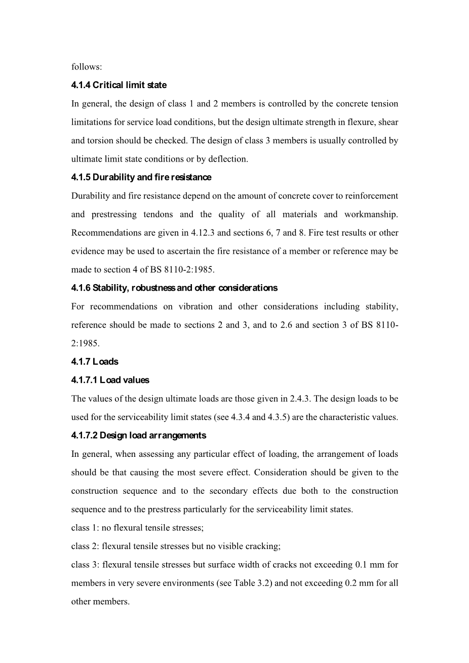
In the assessment of the likely behaviour of a prestressed concrete structure or element, the amount of flexural tensile stress allowed under service load defines its class as follows:
4.1.4 Critical limit state
In general, the design of class 1 and 2 members is controlled by the concrete tension limitations for service load conditions, but the design ultimate strength in flexure, shear and torsion should be checked. The design of class 3 members is usually controlled by ultimate limit state conditions or by deflection.
4.1.5 Durability and fire resistance
Durability and fire resistance depend on the amount of concrete cover to reinforcement and prestressing tendons and the quality of all materials and workmanship. Recommendations are given in 4.12.3 and sections 6, 7 and 8. Fire test results or other evidence may be used to ascertain the fire resistance of a member or reference may be made to section 4 of BS 8110-2:1985.
4.1.6 Stability, robustness and other considerations
For recommendations on vibration and other considerations including stability, reference should be made to sections 2 and 3, and to 2.6 and section 3 of BS 8110-2:1985.
4.1.7 Loads
4.1.7.1 Load values
The values of the design ultimate loads are those given in 2.4.3. The design loads to be used for the serviceability limit states (see 4.3.4 and 4.3.5) are the characteristic values.
4.1.7.2 Design load arrangements
In general, when assessing any particular effect of loading, the arrangement of loads should be that causing the most severe effect. Consideration should be given to the construction sequence and to the secondary effects due both to the construction sequence and to the prestress particularly for the serviceability limit states.
class 1: no flexural tensile stresses;
class 2: flexural tensile stresses but no visible cracking;
class 3: flexural tensile stresses but surface width of cracks not exceeding 0.1 mm for members in very severe environments (see Table 3.2) and not exceeding 0.2 mm for all other members.
4.1.8 Strength of materials
4.1.8.1 Characteristic strength of concrete
The appropriate grade of concrete should be selected from the preferred grades in 6 and 8.5 of Grades C35 and C40 are the minimum recommended for post-tensioning and pre-tensioning respectively. In both cases the concrete strength at transfer should be not less than 25 N/mm2.
4.1.8.2 Characteristic strength of steel
The specified characteristic strengths of prestressing tendons are given in the appropriate British Standards, and those for reinforcement are given in 3.1.7.4.
4.2 Structures and structural frames
4.2.1 Analysis of structures
Complete structures and complete structural frames may be analysed in accordance with the recommendations of 2.5 and 2.6 but, when appropriate, the methods given in 4.3 may be used for the analysis of individual members.
4.2.2 Relative stiffness
Relative stiffness should generally be based on the concrete section as described in 2.5.2.
4.2.3 Redistribution of moments
4.2.3.1 General
Redistribution of moments obtained by elastic analysis may be carried out, for the ULS only, provided the
following conditions are satisfied.
a) Equilibrium between internal forces and external loads is maintained under each appropriate combination of design ultimate load.
b) The reduction made to the maximum design moment within each region of hogging or sagging moments, derived from an elastic maximum moments diagram covering all appropriate combinations of design ultimate load, does not exceed 20 % (but see 4.2.3.2 for certain structures over four storeys).
c) Where the design moment is reduced at a section described in b), the neutral axis depth x should be checked to see that it is not greater than (para;b – 0.5)d,where
d is the effective depth;
para;b is the ratio:
NOTE In general, condition c) will limit or prevent redistribution in cla
剩余内容已隐藏,支付完成后下载完整资料


英语译文共 17 页,剩余内容已隐藏,支付完成后下载完整资料
资料编号:[603518],资料为PDF文档或Word文档,PDF文档可免费转换为Word


