扬州某高校创新大楼(方案1)毕业论文
2020-07-14 22:09:11
摘 要
Abstract 5
第1章 建筑方案说明 7
1.1 设计依据 7
1.2 工程概况 7
1.3 建筑设计 7
1.4 构造做法 9
第2章 结构方案设计 11
2.1 设计依据 11
2.2 工程概况 11
2.3 设计资料 11
2.4 结构平面布置 12
2.5 框架计算单元及计算简图 12
2.6 构件几何尺寸初选 14
2.7 地下室顶板作为嵌固端 18
第3章 荷载统计 20
3.1 恒荷载标准值计算 20
3.2 活荷载标准值计算 23
第4章 水平风荷载作用下的内力计算 24
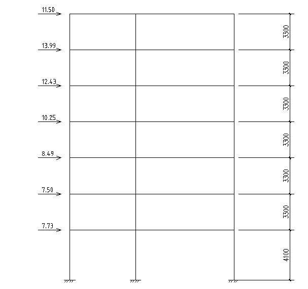
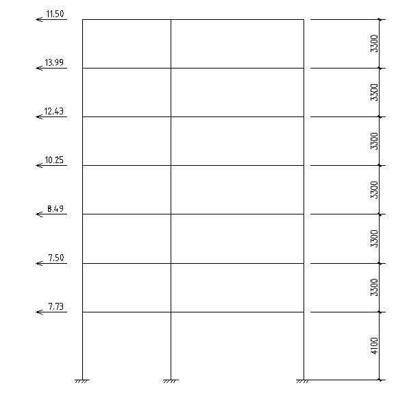
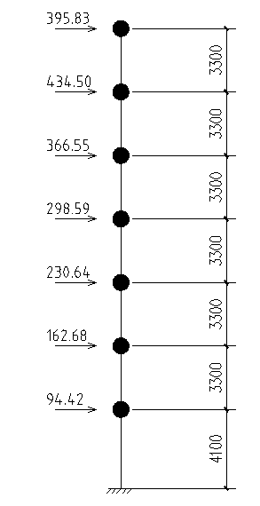
4.1 横向框架在风荷载作用下的计算简图 24
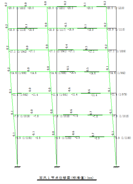
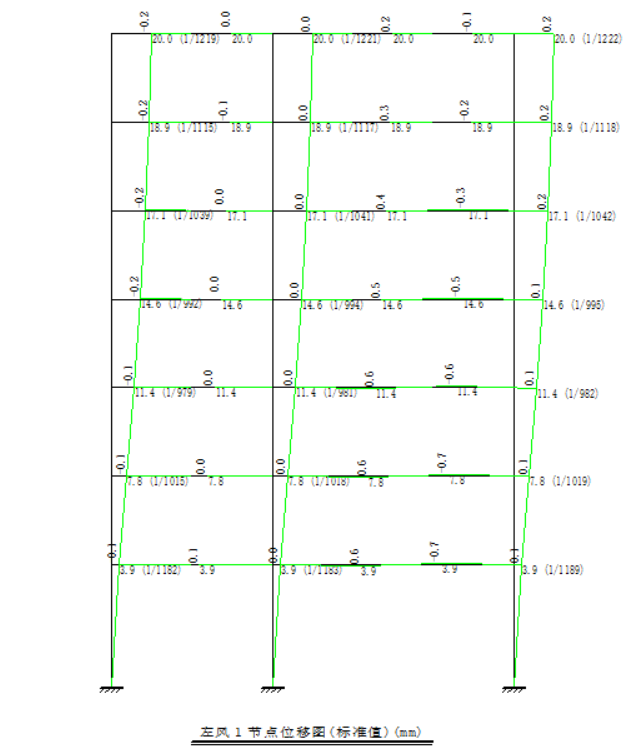
4.2 横向框架在风荷载作用下的位移计算 27
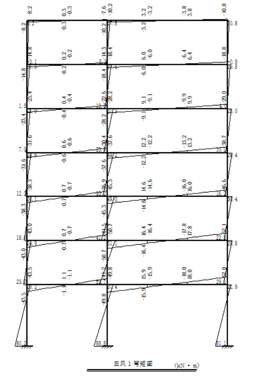
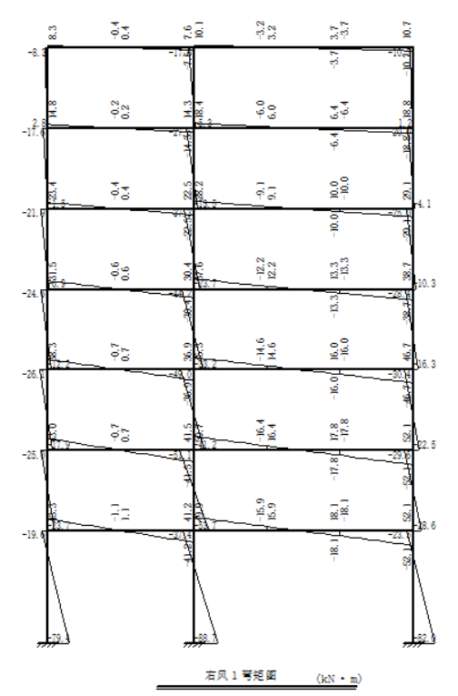
4.3 横向框架在风荷载作用下的内力计算 28
4.4 绘制内力图 31
第5章 水平地震荷载作用下的内力计算 33
5.1 重力荷载代表值计算 33
5.2 横向框架的水平地震作用和位移计算 36
5.3 横向框架在水平地震作用下的内力计算 40
第6章 竖向荷载作用下框架结构内力计算 48
6.1 横向框架在恒荷载作用下的计算简图 48
6.2 横向框架在活荷载作用下的计算简图 51
6.3 横向框架在0.5(雪 活)重力荷载作用下的计算简图 54
6.4 横向框架在恒荷载作用下的内力计算 57
6.5 横向框架在活荷载作用下的内力计算 68
6.6 横向框架在0.5(雪 活)重力荷载作用下的内力计算 72
第7章 内力组合 81
7.1 一般规定 81
7.2 框架梁内力组合 81
7.3 框架柱内力组合 87
第8章 构件截面验算 94
8.1 框架柱截面验算 94
8.2 框架梁截而验算 100
8.3 节点抗震验算 105
第9章 楼板设计 108
9.1 压型钢板的选用 108
9.2 压型钢板的验算 108
9.3 楼板的配筋 111
第10章 节点设计 113
10.1 连接设计 113
10.2 主梁与柱连接计算 113
10.3 主次梁连接节点设计 120
10.4 柱脚设计 122
第11章 基础设计 126
11.1 设计资料 126
11.2 荷载计算 126
11.3 确定基础 126
11.4 筏板基础计算 127
11.5 筏板基础验算 128
11.6 筏板基础柱墩计算 131
11.7 筏板和柱墩配筋计算: 135
第12章 楼梯设计 138
12.1 设计资料 138
12.2 踏步板计算 138
12.3 楼梯斜梁计算 139
12.4 平台梁设计 141
12.5 平台板设计 143
第13章 电算结果 145
参考文献 146
致 谢 147
摘 要
本设计是综合运用所学的专业知识,对江苏省扬州某高校创新大楼(方案1)进行钢结构建筑、结构的设计。本工程为七层钢框架(含地下室一层)创新大楼,总长54m,宽15m,层高分别为:地下室3.6m、底层3.6m,二至六层3.3m,建筑高度为23.4m,总建筑面积约。建筑结构安全等级为二级,设计使用年限为50年,地基基础设计等级为丙级,抗震设防烈度为7度。
设计内容包括建筑设计、结构体系方案选择与结构设计三部分。结构体系方案主要通过比较不同方案抗震性能确定。结构设计包括:一榀横向框架:荷载计算(包括地震作用),要求手算;内力分析,其中恒载、地震作用手算,活载(考虑不利布置)、风荷载上机计算;内力组合与梁柱截面设计,需手算底层、标准层和顶层;其余各层由软件计算,及配合PKPM软件电算,进行构件截面设计、节点设计以及施工图的绘制等。
主体采用钢框架结构,压型钢板布置的楼板。首先确定结构方案并进行荷载统计、梁柱截面选择及刚度验算,然后计算恒载、活载、风、地震作用下的框架内力,经内力组合后得出构件的最不利组合内力,最后进行梁、柱截面验算、节点设计、楼板、楼梯配筋计算,绘制结构图。计算竖向荷载效应时采用弯矩分配法,计算水平荷载效应时采用D值法;计算地震荷载效应时采用D值法;在荷载组合时,考虑以可变荷载效应控制的组合和以永久荷载效应控制的组合方式;在活荷载计算过程中,采用满布荷载法;框架节点设计采用栓焊混合连接的方式;基础采用筏板基础平板式。
关键词:钢结构 建筑设计 内力计算 基础设计
Abstract
This design is the comprehensive use of the professional knowledge learned in the construction of steel buildings and structures for a university innovation building (plan 1) in Yangzhou, Jiangsu Province. This project is a seven-story steel frame (including basement one floor) innovation building with a total length of 54m, a width of 15m, and a floor height of 3.6m in the basement, 3.6m in the bottom, 3.3m in the second to sixth floors, and 23.4m in height. The area is about . The safety grade of the building structure is Grade II, the design service life is 50 years, the foundation design grade is Class C, and the earthquake fortification intensity is 7 degrees.
The design includes three parts: architecture design, structural system scheme selection and structural design. The structural system scheme is mainly determined by comparing the seismic performance of different schemes. The structural design includes: Transverse frame: load calculation (including seismic action), hand calculation; internal force analysis, including dead load, earthquake hand calculation, live load (consider adverse layout), wind load calculation; internal force combination Beam-column cross-section design requires manual calculation of the bottom layer, standard layer, and top layer; the remaining layers are calculated by software and combined with PKPM software for calculation of component section design, node design, and drawing of construction drawings.
The main body of the steel frame structure, pressure plate layout of the floor. First, the structural scheme is determined and the load statistics, beam and column section selection and stiffness check are calculated. Then, the internal force of the frame under constant load, live load, wind and earthquake is calculated. After the internal force combination, the most unfavorable combination force of the member is obtained. , Column section checking, node design, floor, stair reinforcement calculation, drawing structure. The D-value method is used to calculate the horizontal load effect when calculating the vertical load effect. The D-value method is used to calculate the seismic load effect. In the load combination, the combination of the variable load effect control and the permanent load The effect of the combination of control methods; in the live load calculation process, the use of full load method; frame node design using plug welding mixed connection; the basis of the use of raft plate flat.
相关图片展示: