综合楼高层建筑给排水工程设计毕业论文
2020-04-15 21:31:13
摘 要
Abstract 7
一.给水系统 9
1.1给水方式选择 9
1.1.1常见给水方式 9
1.1.2给水方式确定 9
1.2用水定额 10
1.2.1住宅用水定额 10
1.2.2商场用水定额 10
1.3管网水力计算 11
1.3.1管网水力计算方法 11
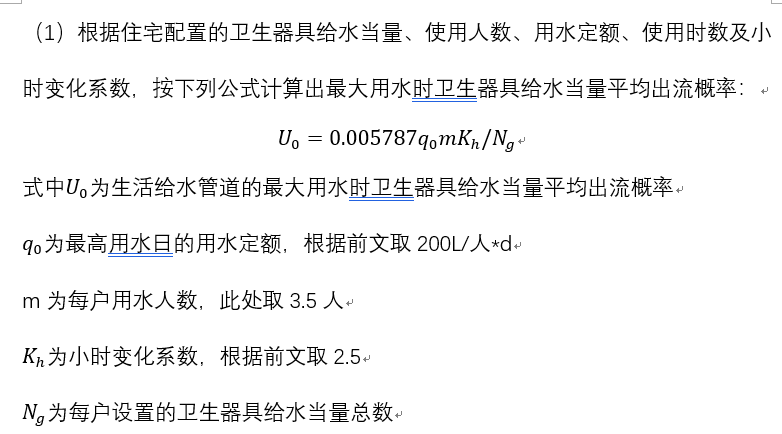
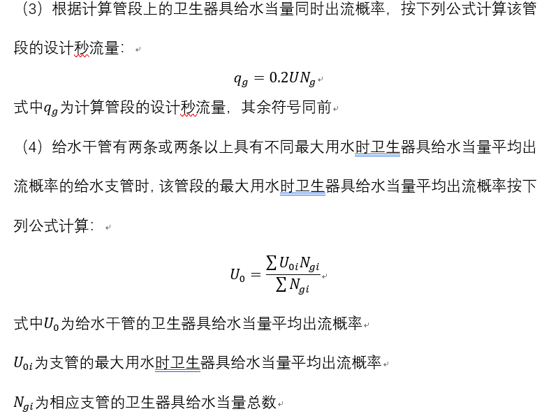
1.3.2设计流量计算 11
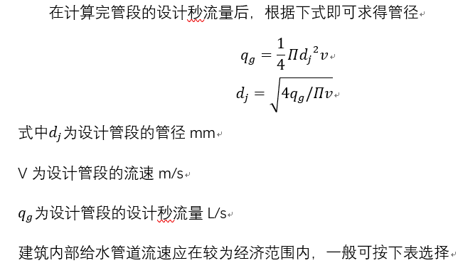
1.3.3管径计算 14
1.3.4设计秒流量及管径计算结果 14
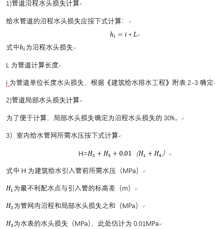
1.3.5水头损失及水压计算方法 24
1.3.6水力计算结果 24
1.4泵房设计 31
1.4.1水泵选型 31
1.4.2泵房尺寸 32
1.5水表设计 32
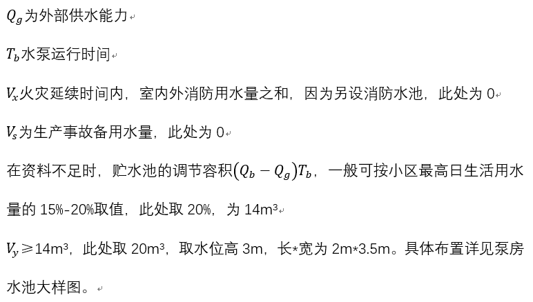
1.6贮水池设计 32
1.7减压计算 33
二.排水系统 35
2.1排水系统选择 35
2.2排水定额 35
2.3设计秒流量 35
2.4排水管道水力计算 36
2.4.1计算规定 36
2.4.2排水横管水力计算 37
2.4.3排水立管计算 37
2.3.5水力计算结果 37
2.5阳台排水及空调冷凝水 45
2.6化粪池设计 46
2.6.1总容积计算 46
2.6.2设计选型 47
2.6.3布置要求 47
2.7集水坑 47
三.雨水排水系统 49
3.1雨水系统选择 49
3.2雨量计算 49
3.2.1设计参数 49
3.2.2雨水流量计算 49
3.3水力计算结果 50
3.4雨水斗 50
四.消火栓系统 51
4.1系统选择 51
4.2基本信息 51
4.3室内消火栓水力计算 51
4.3.1屋顶水箱的设置与计算 51
4.3.2消火栓计算 52
4.3.3 消防给水管网入口压力计算 53
4.4消防水泵设计 54
4.5消防水池设计 54
4.6消火栓减压设置 55
4.7水泵接合器的选定 56
4.8室外消火栓 56
4.8.1室外消防用水量 56
4.8.2布置要求 56
4.8.3设计选型 57
五.自动喷水灭火系统 58
5.1系统选择 58
5.2.基本设计参数 58
5.3喷头布置 58
5.4管道与报警阀布置 58
5.5水力计算方法 59
5.5.1喷头流量 59
5.5.2流速 60
5.5.3水力坡降 60
5.5.4沿程水头损失 60
5.5.5局部水头损失 60
5.5.6总水头损失 60
5.6水力计算结果 61
5.6.1商场 61
5.6.2 02幢住宅 64
5.6.3 03幢住宅 65
5.7水泵设计 66
5.7.1扬程计算 66
5.7.2水泵选型 66
5.8喷淋减压孔板计算 66
设计总结 68
参考文献 69
致谢 70
综合楼高层建筑给排水设计
摘要
本设计为综合楼高层建筑给排水设计,主要包括生活给水系统、消火栓系统、自动喷淋灭火系统、排水系统和屋面雨水排水系统五个系统。
生活给水系统采用竖向分区,一层至四层为低区,由市政管网直接供水; 五层至十一层为中区;十二层至十八层为高区,均采用变频加压供水。采用上行下给的供水方式,由变频无负压调速泵直接向中高区管网供水;生活给水管管材选用PPR塑料管。
建筑室内排水采用污、废水合流制,室外排水采用雨、污分流制。室内一层及以上污废水重力自流排入室外污水管至化粪池,地下室污废水采用潜污泵提升至室外污水管至化粪池。排水立管主要采用伸顶通气方式。排水管采用高密度聚乙烯塑料管;屋面雨水采用重力流雨水斗,外排引向室外市政雨水管网。雨水管采用铸铁管。
根据规范,本建筑为商场和住宅,属二类建筑,火灾危险等级为中危Ⅱ级。消火栓系统、自动喷水灭火系统不分区,消火栓管材采用普通镀锌钢管、喷淋管材采用热镀锌钢管。
关键词: 给水系统 排水系统 消火栓系统 自动喷水灭火系统 雨水系统
Water supply and drainage design for high-rise buildings in comprehensive buildings
Abstract
The design is designed for the water supply and drainage of high-rise buildings in the complex building, which mainly includes five systems: living water supply system, fire hydrant system, automatic sprinkler system, drainage system and roof rainwater drainage system.
The living water supply system adopts vertical division, and the first to fourth floors are low areas, which are directly supplied by the municipal pipe network; the fifth to eleventh floors are the middle areas; the 12th to the 18th floors are the high areas, all of which adopt the variable frequency pressure Water supply. Adopting the water supply mode provided by the upstream, the frequency conversion non-negative pressure speed regulating pump directly supplies water to the middle and high area pipe network; the living water supply pipe material adopts PPR plastic pipe.
The indoor drainage of the building is made of sewage and waste water, and the outdoor drainage is made of rain and sewage. The indoor sewage of one layer or above is discharged into the outdoor sewage pipe to the septic tank by gravity, and the sewage in the basement is raised to the outdoor sewage pipe to the septic tank by the submersible sewage pump. The drainage riser mainly adopts the top extension ventilation mode. The drain pipe is made of high-density polyethylene plastic pipe; the roof rainwater adopts the gravity flow rainwater bucket, and the outer row leads to the outdoor municipal rainwater pipe network. The rainwater pipe is made of cast iron pipe.
According to the regulations, the building is a shopping mall and a residential building. It is a Class II building with a fire hazard rating of Intermediate Stage II. The fire hydrant system and the automatic sprinkler system are not partitioned. The fire hydrant pipe is made of ordinary galvanized steel pipe and the spray pipe is made of hot-dip galvanized steel pipe.
以上是毕业论文大纲或资料介绍,该课题完整毕业论文、开题报告、任务书、程序设计、图纸设计等资料请添加微信获取,微信号:bysjorg。
相关图片展示: