湖北省松滋市某工业园排水工程设计毕业论文
2020-04-07 10:17:10
摘 要
Abstract
Drainage engineering design is an integral part of urban planning. The task of this design is to complete the drainage engineering design of an industrial park in Songzi City, Hubei Province. The scope of the drainage project covers: rain, sewage pipe network engineering and sewage treatment plant engineering.
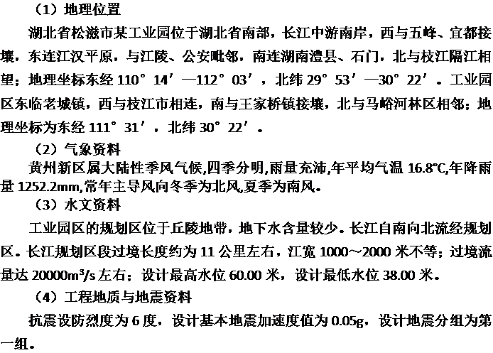
An industrial park in Songzi City, Hubei Province is located in the south of Hubei Province, on the south bank of the middle reaches of the Yangtze River, bordering Wufeng and Yidu in the west, adjoining Jianghan Plain in the east, adjoining Jiangling and public security, and linking Li County, Shimen, and Zhijiang across the river in the south. The industrial park is adjacent to the old town to the east, the west to the Zhijiang City, the south to the Wangjiaqiao Town, and the north to the Maquhe Forest. The design of the terrain is relatively flat.
According to the actual situation in the area, the drainage pipe network adopts the rain and sewage diversion system. Sewage uses two dry pipes to collect the sewage from the two districts and discharge them into the northwest sewage treatment plant located in an industrial park in Songzi City, Hubei Province. The treated water is discharged into the Yangtze River. Based on the principle of the nearest discharge, the rainwater will be divided into 17 sections throughout the urban area. An independent rainwater drainage system will be set up, and the rainwater will be drained into nearby rivers and the Yangtze River.
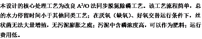
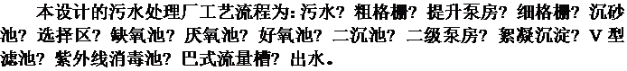
According to the characteristics of the basin and its prevailing wind direction, the sewage treatment plant is located in the northwestern part of the industrial park, with a recent scale of 39,000 m3/d and a long-term scale of 72,000 m3/d. According to the characteristics of treated water and the quality of the effluent, a first-level A treatment is required, and the core biological treatment process is selected to improve the simultaneous nitrogen and phosphorus removal process using the A2/O method. The main process flow is sewage → rough grid → lifting pump room → fine grid → grit chamber → selection area → anoxic tank → anaerobic tank → aerobic tank → secondary sedimentation tank → secondary pump room → flocculation sedimentation → V type filter tank → ultraviolet disinfection tank → bar flow tank → water outlet.
According to the original data provided, in this design, I completed the design and calculation of the drainage pipe system, the rainwater pipe system, and the sewage treatment plant structure of an industrial park in Songzi City, Hubei Province. The drawings include 7 drawings (A1, including one ink line drawing. And hand drawing), complete the design specification and design calculation book.
Key words:SongZi District Drainage Project,Diversion System Drainage System,tertiary Treatment, modified A2 / O Method
目录
摘要 I
Abstract II
第1章绪论 1
1.1设计任务 1
1.2设计成果 1
第二章设计说明书 2
2.1设计原始资料 2
1.1.1城市概况 2
1.1.2自然条件 2
2.2排水工程现状及项目建设的必要性 3
2.2.1排水工程现状 3
2.2.2项目建设的必要性 3
2.3.工程总体方案 3
2.3.1工程服务范围 3
2.3.2排水体制 3
2.4污水量预测 4
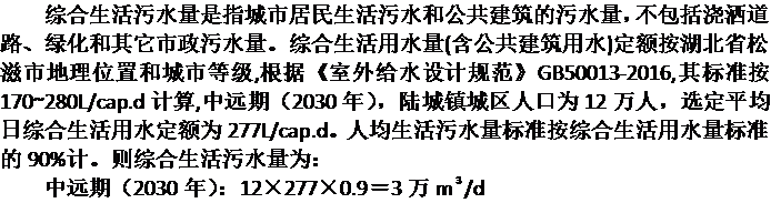
2.4.1综合生活污水量 4
2.4.2工业废水量 4
2.4.3其它污水量 4
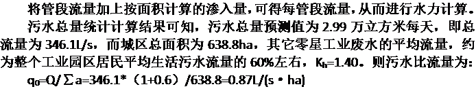
2.4.4污水总量 4
2.4.5污水处理厂厂址选择 5
2.5污水排水工程方案 5
2.5.1排水体制 5
2.5.2污水管道系统布置原则 5
2.5.3雨水管网系统规划 5
2.6污水处理设计 5
2.6.1污水处理工艺的选择 5
2.6.2工艺流程的确定 6
2.6.3污水处理构筑物 6
2.7污泥处理设计 13
2.7.1污泥处理基本方案 13
2.7.2污泥处理构筑物 14
2.8污水厂附属构筑物 14
2.8.3附属构筑物 14
2.9污水厂的总体布置 16
2.9.1污水厂平面布置 16
2.9.2污水厂高程布置 16
2.10排水工程总投资估算 16
2.10.1排水管道工程投资估算 16
2.10.2污水厂工程投资估算 16
设计计算书 17
第3章城市排水方案的确定及计算 17
3.1排水系统体制的选择 17
3.2污水管网设计 18
3.2.1设计要点 18
3.3污水管网水力计算 21
3.3.1污水设计流量计算 21
3.4雨水排水工程方案 24
3.4.1总规确定的规划条件 24
3.4.2雨水管网系统规划 24
3.4.3雨水排放区规划与原则 24
3.4.4规划的技术依据 24
3.4.5雨水管网水力计算 25
第4章污水厂设计方案 26
4.1工程概况 26
4.1.1设计规模 26
4.1.2进出水水质 28
4.2污水工艺流程选择 28
4.3污水厂构筑物工艺设计 31
4.4格栅 31
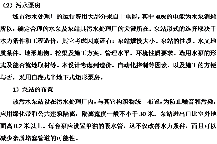
4.5污水提升泵房 34
4.5.1水泵设计 34
4.5.2集水池设计 35
4.6.泵后细格栅 36
4.7沉砂池的设计计算 38
4.7.1设计要点 38
4.7.2设计参数 38
4.7.3设计计算 38
4.8A2/O反应池的设计计算 39
4.8.1设计参数 40
4.8.2设计计算 41
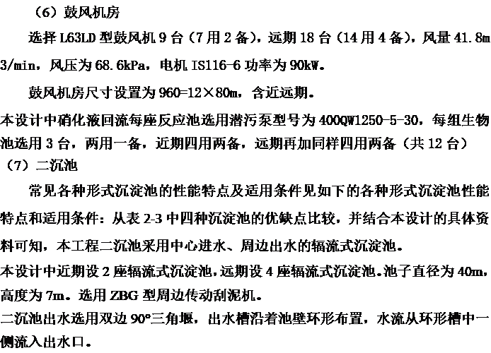
4.9辐流二沉池 48
4.9.1设计参数 48
4.9.2设计计算 48
4.10化学除磷 55
4.10.1混凝剂的配制和投加 55
4.10.2加药间及药库 58
4.10.3混合设备的设计 59
4.11网格絮凝池 60
4.11.1设计参数 60
4.11.2设计计算 61
4.12斜管沉淀池 65
4.12.1设计参数 65
4.12.2平面尺寸计算计算 66
4.12.3进出水系统 67
4.14V型滤池 70
4.14.1正常过滤系统设计 72
4.14.2反冲洗系统设计 78
4.14.3反冲洗泵房设计 80
4.15紫外消毒 83
4.15.1设计参数 83
4.15.2设计计算 83
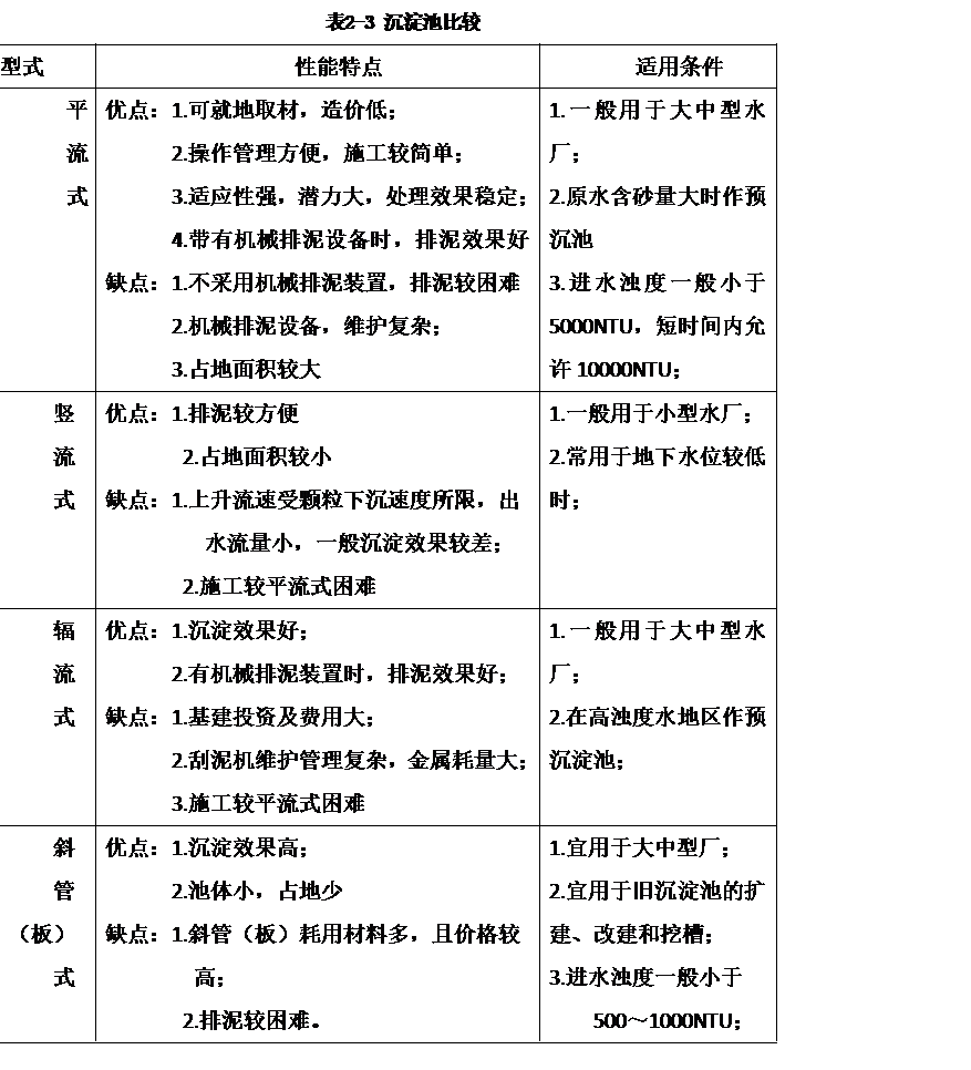
4.16计量设备 84
4.17污泥处理构筑物 86
4.17.1剩余污泥量计算 86
4.17.2污泥浓缩池设计 87
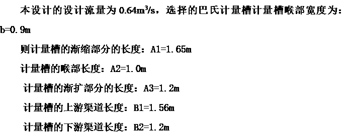
4.17.3贮泥池 90
4.17.4脱水设计 92
第5章水厂总体布置 95
5.1主要构建筑物 95
5.2附属构建筑物 96
5.3平面布置 99
5.4高程布置 100
第6章排水工程总投资估算 106
6.1排水管道工程投资估算 106
6.2污水厂工程投资估算 106
6.3远期规划附加投资估算 106
第9章总结 107
第10章参考文献 108
第11章附录 110
第12章致谢 136
第1章绪论
1.1设计任务
接受毕业设计任务的学生应在规定的时间内完成湖北省松滋市某工业园的排水设计。
排水工程设计范围包括:雨、污水管网工程与污水处理厂工程。
1.2设计成果
1、毕业设计说明书(附计算书)
毕业设计说明书、计算书一般为60~90页(约3万~5万印刷字符),应包括目录、前言、正文、小结及参考文献等,学生必须用英文书写毕业设计摘要(300中文单词)。
2、毕业设计图纸
毕业设计图纸的数量不得少于6张(按1号图计)。图面应布局合理、正确清晰、用工程字注文、符合制图标准及有关规定。
在绘图能力方面要求:
(1)至少有1张图纸用CAD绘制;
(2)至少有1张图纸用铅笔绘制;
(3)墨线底图数量不得少于1张。
在设计深度方面要求:至少有1张图纸基本达到施工图要求。
第二章设计说明书
2.1设计原始资料
1.1.1城市概况
 1.1.2自然条件
 2.2排水工程现状及项目建设的必要性
2.2.1排水工程现状
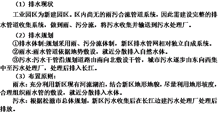 2.2.2项目建设的必要性
2.3.工程总体方案
2.3.1工程服务范围
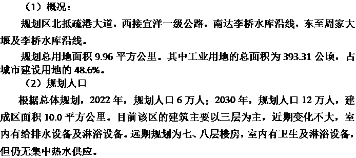
根据总体规划,本工程服务范围为:2022年,规划人口6万人;2030年,规划人口12万人,建成区面积10.0平方公里。
2.3.2排水体制
采用雨污分流式排水体制
2.4污水量预测
设计年限:中远期:2030年
2.4.1综合生活污水量
 2.4.2工业废水量
工业园区规划除造纸厂为主要排水大户外,还有一些零星工厂企业。其中造纸厂日平均污水量(厂内处理后达到排入下水道标准)近期为10000m3/d,远期为20000m3/d,Kh=1.50。其它零星工业废水的平均流量,约为整个工业园区居民平均生活污水流量的60%左右,Kh=1.40。工业废水量造纸厂以大用户集中流量的方式进入管网。其他零星工业废水按比例以生活污水相同的方式进入管网。详细计算见计算表格。
2.4.3其它污水量
其它污水量是指地下水渗入量。静止水位埋深5.0m左右。地下水渗入量确定为:600m3/km2·日。
2.4.4污水总量
2.4.5污水处理厂厂址选择
污水干管沿规划道路由南向北敷设干管,城市污水逐步由东向西集中至污水处理厂,处理后尾水排入长江。
2.5污水排水工程方案
2.5.1排水体制
远期采用完全分流制排水体制
2.5.2污水管道系统布置原则
(1)根据工业园区地形特点与污水厂、出水口位置,充分利用地形,在低洼处布置干管和主干管,避免污水提升。由于该工业园区地势变化有规律,面积较大且较为平坦,布置的时候采用环绕式。
(2)尽量减少污水管道穿越河流等较大障碍物以及国道等高级道路,以减少工程量与工程投资。
(3)污水管道坡降尽可能与地面坡降一致,以减少管道埋深。
2.5.3雨水管网系统规划
根据雨水管道布置要求及当地地形特点,宜就近排水,共设置17个出水口,根据地形与距离11—15和17排向长江,其余就近排入水体。
2.6污水处理设计
2.6.1污水处理工艺的选择
 2.6.2工艺流程的确定
 .3污水处理构筑物
- 粗格栅
 粗格栅外形尺寸为:L×B×H=2.3×1.1×0.9m则粗格栅间外形尺寸按远期设置为:L’×B’×H=2.3×5.6×0.9m。粗格栅除污机近期选用两台GH-1100回转式格栅除污机,远期选用四台栅渣采用带式输送机输送。
 2)泵房内部的排水
由于泵房较深,采用电动排水。
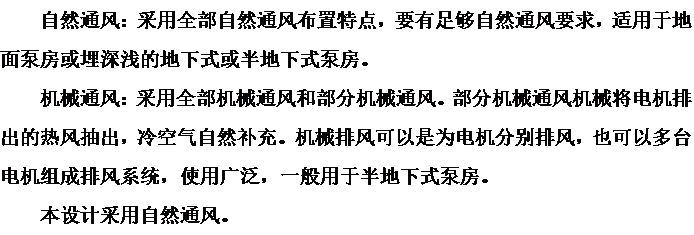
3)泵房的通风设施
 4)泵选型
4)泵选型
表2-2泵房方案优缺点比较表
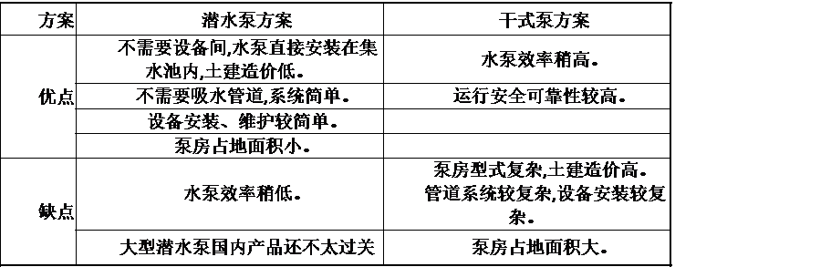 进水泵房形式有两个方案可供选择,潜水泵房方案和干式离心泵房方案。两个方案的优缺点比较见表2-2所示。
 细格栅尺寸为:L×B×H=3.7m×1.5m×1.1m
细格栅除污机近期选用2台XWB-Ⅲ-2-2.5背耙式细格栅除污机,远期四台。
则细格栅间外形尺寸按远期设计为:L’×B’×H=3.7×4.6×1.1m
(4)沉砂池
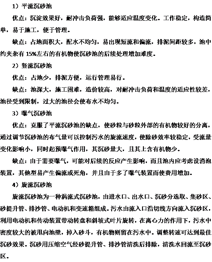 基于以上四种沉砂池的比较,本工程设计确定采用旋流沉砂池。
近期采用两座旋流式沉砂池Ⅰ型号即钟式沉砂池,远期设四座。每座流量为Q=0.32m3/s,D×H=1.5m×3.15m。
(5)A2/O反应池
本设计中近期设合建式2座A2/O反应池,远期设4座A2/O反应池,则每座A2/O反应池流量为812.5m3/h。
A2/O反应池由四个反应池合建,反应池设置为厌氧池1个廊道,缺氧池1个廊道,好氧池3个廊道,厌氧区初始长度的1/7作为选择区。每个廊道之间用导流墙隔开。反应池的有效水深取h=5m。缺氧池和厌氧池和好氧池廊道宽度为 ,廊道长度均为41m。则A2/O反应池的尺寸为:L×B’×H=41.6m×87.8m×6.4m。
本设计中曝气系统采用鼓风曝气系统,曝气装置选择球冠形橡胶膜微孔曝气器,设在距池底0.2m处,淹没水深为4.8m。
以上是毕业论文大纲或资料介绍,该课题完整毕业论文、开题报告、任务书、程序设计、图纸设计等资料请添加微信获取,微信号:bysjorg。
相关图片展示: