泰州人民医院办公楼给排水设计毕业论文
2020-07-08 21:47:33
摘 要
本工程为泰州人民医院办公楼给排水设计项目。该办公楼为10层,建筑总高度为39.9m,负一层为地下车库,层高4.5m,一层层高4.5m,标准层高3.6m,屋顶楼梯间层高2.4m,女儿墙上檐口标高39.9m。地上建筑总面积(不含地下)为 ,地下一层面积为
 ,标准层
,标准层 。
。
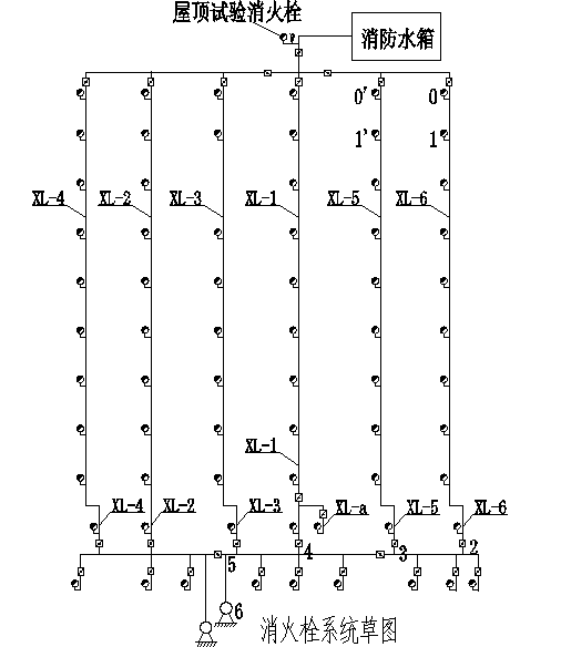
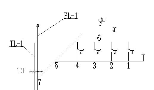
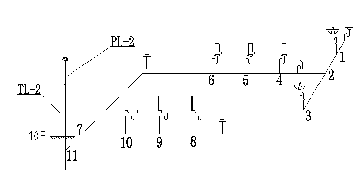
给水系统采取垂直分区并联给水的方式,从市政管网引两根引入管进入建筑,负一层至地上五层由市政管网直供,六层至十层由无负压变频供水设备加压供水。本建筑属于二类高层民用建筑,耐火等级为二级,室外消火栓用水量 ,室内消火栓用水量
 。消火栓充实水柱高度13m,水龙带长度25m。在屋顶层设试验消火栓一个,每个室内消火栓箱内均设有远距离启动消防泵的按钮。本建筑喷淋系统采用湿式自动喷水灭火系统,地上部分为中危Ⅰ级,地下部分为中危Ⅱ级,分两个区,负一至四层为低区,五至十层为高区。报警阀设于地下室泵房内,各层均设水流指示器、信号阀和末端试水装置,其信号均送入消防控制中心进行处理。建筑内消防及喷淋在火灾前10min用水由屋面箱泵一体化消防增压稳压设提供,有效容积为
 ,后期灭火用水由地下一层的消防水池提供,其有效容积为
 ,分为两格。
室内外排水均采用污废合流制,经检查井直接排入市政污水管。排水立管采用通气立管的双立管排水系统,其中一层单独排水,二至十层集中排水。地下室排水经排水沟汇集排至集水坑,经潜污泵提升排至检查井。建筑屋面雨水排水系统采用内排水系统,选择重力半有压流系统,雨水经屋面雨水斗收集后由雨水立管排入市政雨水管网。
关键词:给水系统 排水系统 消火栓系统 自动喷水灭火系统 雨水系统
Supply and drainage design
Abstract
This project is a water supply and drainage design project for the Office building of the people's Hospital of Taizhou. The total height of the building is 39.9m, the negative first floor is the underground garage, the floor height is 4.5m, the standard floor height is 3.6m, the roof staircase height is 2.4m, the daughter wall cornice height is 39.9m. The total area of the above ground building (excluding underground) is 9768.7m2, the area of the first basement is 2989m2, and the standard layer is 976.8m2.
The water supply system adopts the method of vertical division and parallel connection, which leads two pipes into the building from the municipal pipe network, the negative one floor to the ground five layer is directly supplied by the municipal pipe network, and the six to ten stories are supplied by pressurized water supply equipment without negative pressure frequency conversion water supply equipment. The building belongs to the second-class high-rise civil building, the fire resistance grade is two, the outdoor hydrant water consumption is 40L / s, the indoor hydrant water consumption is 20L / s.
The water column height of hydrant is 13 m and the length of water hose is 25 m. A test hydrant is installed on the roof. Each indoor hydrant box is equipped with a remote fire pump button. The sprinkler system of this building adopts the wet automatic sprinkler system. The ground part is medium dangerous grade I, the underground part is medium dangerous grade II, it is divided into two areas, negative one to four layers is low area, five to ten stories is high area. The alarm valve is located in the basement pump room, each layer is equipped with water flow indicator, signal valve and terminal water testing device, and the signals are all sent to the fire control center for processing. The 10min water for fire fighting and sprinkling in the building before fire is provided by the roof box pump integrated fire pressurization and stable pressure device, the effective volume is 18m3, and the later fire extinguishing water is provided by the fire water pool on the first floor of the ground floor. The effective volume of the water is 545m3, which is divided into two boxes.
The indoor and outdoor drainage adopts sewage combined flow system and is discharged directly into municipal sewers through inspection wells. The drainage riser uses a double riser drainage system with a single layer and two to ten layers of centralized drainage. The basement drains are collected by drains to the catchment pits and lifted by submersible pumps to the inspection wells. The Rain Water drainage system of building roof adopts the internal drainage system, and the gravity semi-pressure flow system is chosen. The Rain Water is collected by the roof Rain Water bucket and discharged into the municipal rainwater pipe net by Rain Water riser.
Keyword: water-supply system;drainage system;fire hydrant system;automatic sprinkler system;rainwater system
目 录
给排水设计 Ⅰ
摘 要 Ⅰ
Abstract Ⅱ
设计说明书 1
第一章 项目概述 1
1.1 工程概况 1
1.2 设计依据 1
1.3 工程设计内容 1
第二章 生活给水系统方案 2
2.1 给水系统方案选择 2
2.2 给水系统的组成 3
2.3 给水管材和附件 4
2.3.1 给水管材 4
2.3.2 给水附件 4
2.4 给水管道布置和敷设 4
第三章 消防系统方案 6
3.1 室内消火栓系统 6
3.1.1 消火栓系统的选择 6
3.1.2系统组成 7
3.1.3设备及构筑物 7
3.1.4消火栓的安装 7
3.2 自动喷淋系统 7
3.2.1室内自动喷水灭火系统的选择 7
3.2.2系统组成 8
3.2.3喷头的选择与布置 8
3.2.4设备及构筑物 9
3.2.5喷淋系统的安装 9
第四章 生活排水系统方案 10
4.1 排水系统方案选择 10
4.2 排水系统的组成 10
4.3 排水水管材和设备 10
4.4 排水管道布置和敷设 11
4.5 通气管的安装 11
4.6 检查口、清扫口和检查井的设置 12
第五章 雨水排水系统方案 13
5.1 雨水排水系统方案选择 13
5.2 雨水排水系统的组成 13
5.3 雨水管道的敷设与布置 13
设计计算书 14
第六章 生活给水系统计算 14
6.1 用水定额及用水量 14
6.1.1 给水用水定额及时变化系数 14
6.1.2 最高日用水量 14
6.1.2 最高日最大时用水量 14
6.2 设计秒流量 14
6.3 给水系统水力计算 14
6.3.1 各卫生器具的流量、当量、连接管管径及最低工作压力 15
6.3.2 市政直供部分水力计算 15
6.3.3 高区无负压给水设备供水部分水力计算 18
6.4 水表选型 20
6.4.1 选型要求 20
6.4.2 水表选型及水头损失计算 20
6.4.3 水表的安装 21
6.5 市政直供部分所需压力校核 21
6.6 高区设备选型与所需压力校核 21
6.6.1 高区给水系统所需压力 22
6.6.2 设备选型 22
6.6.3 减压阀设置 23
第七章 消火栓系统计算 25
7.1 消火栓的布置 25
7.2 消火栓的水压 25
7.2.1 水枪喷嘴处所需水压 25
7.2.2 水枪喷嘴出水量 26
7.2.3 水带阻力 26
7.2.4 消火栓栓口所需水压 26
7.3 消火栓系统水力计算 26
7.4 消防泵选择 29
7.5 消火栓系统减压计算 29
7.6 消防箱配置 29
7.7 灭火器配置 29
7.8 水泵接合器 29
7.9 消防贮水池 29
7.10屋顶消防水箱 31
第八章 自动喷淋系统计算 32
8.1 设计基本参数 32
8.2 管道与报警阀布置 32
8.3 喷头的选用与布置 32
8.4 系统的设计流量 33
8.5 水力计算(特性计算法) 33
8.5.1 低区喷淋水力计算 34
8.5.2 高区喷淋水力计算 39
8.5.3 系统水力计算 43
8.6 增压与贮水设备 42
8.6.1 喷淋泵选择 43
8.6.1 消防水池、消防水箱与稳压设备 43
8.7 水泵接合器 43
8.8 喷淋减压孔板计算 43
8.8.1 减压孔板计算 43
8.8.2 负一层设置减压孔板后压力校核计算 44
第九章 生活排水系统计算 48
9.1 设计秒流量 48
9.2 卫生器具当量和排水流量 48
9.3 排水横支管水力计算 49
9.4 排水立管水力计算 53
9.5 排水通气立管选用 53
9.6 排水排出管水力计算 54
相关图片展示: