小型步进电机控制器设计毕业论文
2020-04-15 21:00:32
摘 要
步进电机是机电控制中常用的执行机构,大范围地应用在数控机床、汽车制造、产品生产流水线等各种制造业的场合中。因为开环的控制特性,步进电机速度与位置的精确控制是人们孜孜不倦的追求目标。
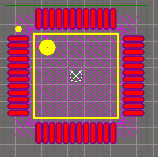
本文首先借助电路设计软件平台AD18,完成基于stm32f103c8t6的核心系统板各个模块的电路原理图和PCB设计,其次以stm32f103c8t6核心系统板作为步进电机控制系统的主控制器,搭配专为两相四线步进电机设计生产的驱动芯片TB67S109A作为驱动设备,选用42型双极性两相四线步进电机作为控制对象,完整地实现了一个步进电机控制系统。
接下来,本文针对小型步进电机在运行过程中出现的失步与过冲的问题与原理进行了详细的分析。通过搭建梯形加减速的算法模型,利用Keil软件平台进行算法程序的编写与开发,在实现步进电机驱动的基础上,进一步实现了控制电机加减速的目标,从而解决了步进电机在启停过冲中出现的失步与过冲现象。
关键字:微型步进电机 控制器设计 开环控制 加减速控制
Abstract
Stepper motor is a commonly used displacement conversion device , which is widely used in various manufacturing occasions such as CNC machine tools, automobile manufacturing, and mechanical arms of product production lines.Due to its open-loop characteristics, the finer control of the stepper motor speed and position is the goal of people's tireless pursuit.
This paper firstly completes the circuit schematic and PCB design of each module of the core system board based on stm32f103c8t6 by means of circuit design software platform AD18.Secondly, the core system board of stm32f103c8t6 is used as the main controller of the stepper motor control system,with the driver chip TB67S109A designed and manufactured for two-phase four-wire stepper motor as the driving device,select type 42 bipolar two-phase four-wire stepper motor as the control object,completely implemented a stepper motor control system.
Next, this paper analyzes the problems and principles of out-of-step and overshoot that occur during the operation of small stepping motors,by constructing the algorithm model of trapezoidal acceleration and deceleration, the Keil software platform is used to compile and develop the algorithm program,on the basis of the realization of the stepping motor drive, the goal of controlling the motor acceleration and deceleration is further realized, thereby solving the step-out and overshoot phenomenon of the stepping motor in the start-stop overshoot.
Key Words: Micro stepping motor ;Controller design ;Open loop control;
Acceleration and deceleration control
目录
摘要 I
Abstract II
第一章 绪论 1
1.1国内外研究背景及现状 1
1.2课题主要工作 2
第二章 步进电机控制方案设计 4
2.1总体结构介绍 4
2.2 步进电机控制方法的选用 4
第三章 步进电机控制系统硬件设计 6
3.1控制器芯片选型 6
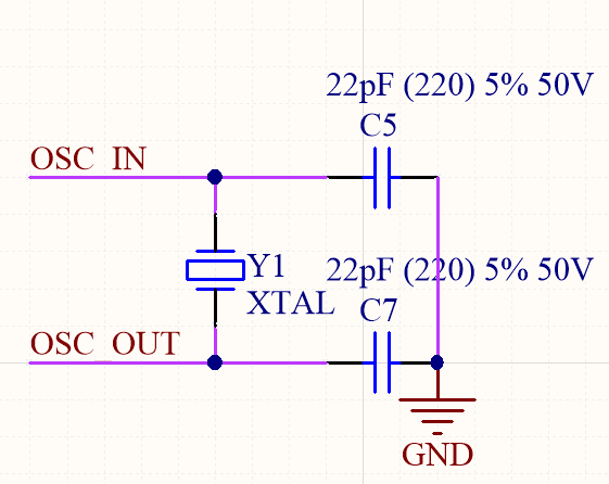
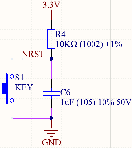
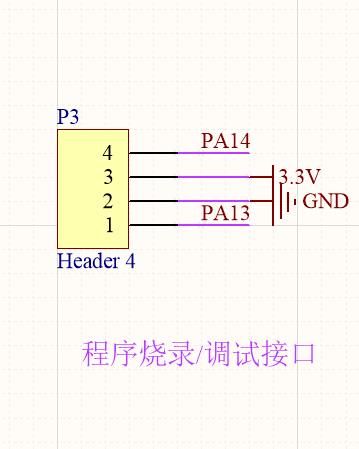
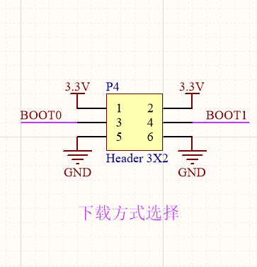
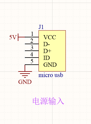
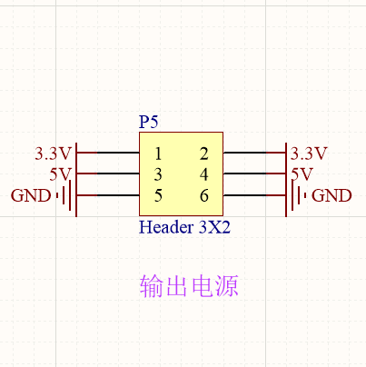
3.2 控制器硬件电路设计 6
3.3驱动器选型与硬件介绍 13
3.4 步进电机的选型与硬件介绍 16
3.5 通信方法设计及硬件选型 16
3.6 步进电机控制系统硬件的连接 18
第四章 步进电机控制系统软件设计 20
4.1步进电机基本旋转的实现 20
4.2 基于梯形加减速的步进电机控制 21
4.2.1步进电机曲线加减速 21
4.2.2梯形加减速算法原理分析 23
4.3梯形加减速算法实现 32
第五章 步进电机系统测试 33
5.1 硬件调试 33
5.2 步进电机控制系统测试 34
第六章 总结与展望 36
6.1总结 36
6.2展望 36
参考文献 38
致谢 41
- 绪论
控制器又称微型化的计算机,是将计算机上的各个功能芯片简化并集成到一个芯片上的设备,因其体积小巧、控制方法多样、硬件设计灵活、控制稳定等特点,早在控制器问世之初,人们就将控制器应用在电机的控制上,替代并淘汰了人工控制电机的方式。现今,得益于控制器发展越来越智能,性能愈加全面的趋势,控制器与步进电机结合的驱动控制方式更加发挥了步进电机的优势,使其在制造业的领域中应用得更加广泛。
小型步进电机的控制器属于步进电机控制系统的核心组成部分,决定着步进电机的控制方式和控制精度,同时也是制造业中应用最为广泛的元器件之一。在微型计算机发明以前,步进电机脉冲信号的控制是由硬件来实现,由单独的元件组成控制电路,安装复杂,需要耗费大量的元器件,完成之后,便不能对系统做出调整,如需调整,则需要重新设计电路[1]。这也决定了针对不同的步进电机或者不同的工作模式必须分别设计相应的驱动器,开发设计难度大,成本高,阻碍了本进电机的进一步发展[1]。
以上是毕业论文大纲或资料介绍,该课题完整毕业论文、开题报告、任务书、程序设计、图纸设计等资料请添加微信获取,微信号:bysjorg。
相关图片展示: