Research of ABB Robot Control System毕业论文
2020-04-15 18:04:39
摘 要
当前,工业机器人话题已经成为国内外普遍关注的热点。据报道,世界的工业机器人市场正在急剧扩大,尤其是正在进行产业升级的中国,工业机器人的应用更是在快速普及。所以工业机器人的应用技术变得更加重要。
针对上述因素,本文提出了基于ABB的六关节工业机器人的运动轨迹的控制和设计。本课题所做的工作主要有两个:一是用ABB公司的IRB4600工业机器人做几个常见及常用图形的轨迹运动的控制和实现。二是用ABB另一款机器人IRB1410做一个接近于用于制造现场应用的玻璃涂胶轨迹的工作站。基于机器人集成的控制功能,用其自带的专用示教器和控制器通过编程RAPID程序来生成几个既定的轨迹。并通过ABB公司的Robo Studio软件来实现离线的编程及仿真。
最后通过仿真及实验结果的验证,本论文对指导机器人的相关应用有一定的作用。
关键词:工业机器人 ABB 轨迹实现 系统仿真等等
Abstract
In this modern world Robot has become one of the important parts of our life. It is broadly needed in local and international market as well. Especially in China where industrial upgrading is taking place, the application of industrial robots is rapidly spreading.
In view of the above factors, this paper proposes the control and design of the motion trajectory of the six-joint industrial robot based on ABB. There are two main tasks in this project: First, use ABB's IRB4600 industrial robot to control and implement the trajectory movement of several common and commonly used graphics. The second is to use ABB's other robot, the IRB1410, as a workstation close to the glass gluing track used for manufacturing field applications. Based on its function, an established trajectory is generated by programming the RAPID program with its own dedicated teach pendant and controller. And through ABB's Robo Studio software to achieve offline programming and simulation.
Finally, through the simulation and experimental results, this article will show the details the relevant applications of the robot.
Keywords: industrial robot; ABB; trajectory realization; system simulation etc.
Contents
摘要 ………………………………………………..I
Abstract ………………………………………………………………………………………….II
Contents…………………………………………………………………………………………………04
Chapter I Introduction ...………………………………………………………………………………….06
1.1 Background of topic selection ……………………………………………………………………. ….06
1.2 Research status and development trend at home and abroad …………………………………………07
1.3 The main research contents of this paper …………………………………………………………….10
1.3.1 Main Contents……………………………………………………………………………………....10
1.3.2 Basic Requirements and Key Problems to be Solved.………………………………………...……10
Chapter II Selection and Demonstration of Trajectory Control Design Schemes 6……………………....11
2.1 Overall scheme selection and demonstration …………………………………………………….…...11
2.2 Program Selection and Demonstration of Tools ...…………………………………….……………14
2.2.1 Tools for Graphic Track and Their Tool Coordinate System…...…………………………….…….14
2.2.2 Tools for Glue Coating Track of Glass and Their Tool Coordinate System ….……………………15
2.3 Scheme Selection and Demonstration of Work piece …….…………………………………….……17
2.3.1 Work piece with graphical trajectory and its work piece coordinate system …. ……………….….17
2.3.2 Work piece with Glue Coating Track and Its Work piece Coordinate System.………………….…18
2.4 Programming Language Scheme Selection and Demonstration ………………………………….….19
Chapter III Design and Selection of System Hardware.………………………………………………….20
3.1 Total Hardware Composition of the System ……………………………………………………….…20
3.2 Hardware of Graphic Trajectory Control System …………………………………………………….20
3.2.1 IRB4600 Robot …………………………………………………………………………………….20
3.2.2 IRC5 Compact Controller and Instructor ….…………………………………………………….…22
3.2.3 DSQC651 Communication Board ………………………………………………………………….23
3.3 Hardware of trajectory control system for glass coating.………………………….…………………23
3.3.1 IRB1410 Robot ….……………………………………….…………………………………………23
3.3.2 DSQC652 Communication Board ……………………….…………………………………………25
Chapter IV Design of System Software Part.…………………….………………………………………26
4.1 Robot Studio Software Platform …...…………………………………………………………………26
4.2 RAPID Programming Language …...…………………………………………………………………26
4.3 Program Module Division and Design. ………………………………………………………………27
4.3.1 Graphic Trajectory Programming ………………………………………………………………….27
4.3.2 Glue Coating Track Programming for Glass ….……………………………………………………31
Chapter V Trajectory Debugging and Operation …………………………………………………………35
5.1 Debugging and Operation of Graphic Trajectory …………………………………………………….35
5.2 Adjustment and Operation of Glue Coating Track for Glass ….…………………………………….39
Chapter VI Summary and Prospects ………………………………………………………………...…. 42
6.1 Summary ………………………………………………………………………………………. …….42
6.2 Prospects …………………………………………………………………………………………...…43
References ……………………………………………………………………………….………...….…44
Thankful ….…………………………………………………………………………………………...….47
Appendix A Graphic Track Program ………………………………………………………………….…48
Appendix B Glue Coating Track Procedure …………………………………………….…………….…53
Chapter I. Introduction
1.1 Background of this topic
As we all know, the all kind of robot is a highly automated device that resembles the human body or some part of the human body in shape and has similar functions to the human body. And for the coming era of advanced manufacturing and intelligent or personalized manufacturing, it is an indispensable part. Of course, robot has some other characteristics too. But its function is relatively single at present, and its environmental adaptability needs to be improved. In this paper, the robots we study are mainly industrial robots for industrial production. Industrial robots are the most mature, widely used and relatively low-cost class of robots. The ability to develop industrial robots and industrialize them has become an important indicator of a country's high-end technological innovation and manufacturing level. Developed countries have formulated the development strategy of industrial robots and vigorously developed the industry of industrial robots. What we should do is try our best to occupy the advanced manufacturing market in the future and improve the level of our own industrial manufacturing. Industrial robots have been applied in many industries, and the quality of products has been greatly improved while ensuring the production efficiency. For example, in our well-known automotive manufacturing, electronic semiconductors, household appliances manufacturing, building supplies, machinery manufacturing and other fields, a large-scale use of highly integrated robotic automation production lines. Because most of these products are manufactured in harsh environments, it can ensure workers ‘health and improve their working environment quality
After the 21st century, although the world industrial structure and economic structure are undergoing significant and in-depth changes. But for a long time, manufacturing industry has been the focus of investment and attention of many countries in the world. Because it is an important way a country's economic strength and extensive national power in a very short time. Especially for China, which is transforming from agricultural dominance to industrial dominance. At present, China is still a manufacturing country that is making every effort to industrialize. In the foreseeable future, the main economic body of our country is still the manufacturing industry which affects people's livelihood. And in the following world economic restructuring. However, since the new century, although China's manufacturing industry has made considerable progress, there is still a big gap compared with the developed countries in the West. Especially in the manufacturing technology of core components, because our industrial base is relatively weak, the core manufacturing technology of many high-performance equipment still depends on foreign countries. For example, the key components of industrial robots: reducers and high-performance servo motors. Although some domestic companies are doing it, there are still many things worth improving in terms of control accuracy and durability compared with developed countries such as Japan, Germany and so on.
As China's economic and social structure changes, the wages of the labor force are also rising, and the advantage of the past demographic dividend is also decreasing. The transformation of manufacturing technology to intelligence, flexibility and individuality urgently calls for the construction of a new manufacturing system. Industrial robots are the core equipment of manufacturing industry in the future. Therefore, accelerating the development of industrial robotics industry is conducive to recapturing the advantages of China's manufacturing industry. In addition, China has also put forward the development strategy of "Made in China 2025", which also brings the robot industry into the level of national development strategy.
1.2 Research status and development trend at home and abroad.
With the rise of labor costs and the improvement of product quality requirements in manufacturing industry, the deep integration of industrialization and in formalization is inevitable, and the demand for industrial robots is also growing. However, at present, although domestic institutions and companies attach great importance to and make great progress in the research of industrial robots, such as Xinsong, Eston, etc., although they have their own advantages in robot controller and user interface, there is no big gap compared with foreign companies, but there is a big gap in the main core technology and accessories of robots, such as reducer, high-performance servo. Electrical machinery, although domestic companies do, but its accuracy and durability indicators are still catching up with several foreign companies. Especially ABB in Switzerland, KUKA in Germany, Kawasaki Heavy Industry in Japan, Ankawa Electric Machinery and Fanaco. The research on trajectory control of industrial robots varies from company to company in different ways. Most of them are controlled by their special programming language. The programming language varies from company to company, but it is similar in general. In addition, there are other control modes such as MCU, PLC or motion control card. The main control methods studied in recent years are as follows:
1. Industrial Robot Control System Based on Bus Mode
This control method can make the hardware control system of industrial robots more concise, thus effectively reduce the cost of hardware control of industrial robots, and because the bus uses digital signals, transmission has better stability. At present, there is a kind of real-time trajectory control for industrial robots by using Ether CAT bus on X86 platform. Essentially, it uses the extensibility of the Windows kernel to create a bus-based intelligent manufacturing platform, so as to build a real-time industrial robot control system. In addition, on the premise of drawing the advantages of existing schemes, some studies have proposed the industrial robot control mode based on this kind of bus. However, this kind of control card is based on personal computer as the core hardware, supplemented by motion control card, and can support bus transmission. In addition, some control hardware such as servo motor and I/O communication board are added. With Linux as the main control language, industrial robots can be controlled by adding control algorithms and writing programs. This control scheme can customize user interface. Human-computer interaction is very friendly. In practice, the control technology has broad application prospects. The control method basically meets the field control requirements of industrial robots.
2. Industrial Robot Asynchronous Serial Communication Relay Control System Based on Single Chip Microcomputer.
The flexibility and ease of use of MCU are well known, besides, its cost is low. Because most industrial robots integrate a common serial communication protocol on their controllers, users can connect relevant controllers and program through the serial port. Of course, for ABB industrial robot, users can control the robot through its special control system and language, but because of the specialty and specialty of its robot programming language, the control of its serial port is not flexible, so it cannot read data in time and also non conducive to the real-time and reliability of control. This situation can be solved by building a communication relay system connected with industrial robot controller serial port with single chip computer such as STM32 as the hardware core. It processes the serial data of the robot through the interrupt signal of the single chip computer to gain the control of real time. The communication relay system with STM32 MCU as the core can trigger the interrupt of the controller by switching on the signal and read the serial data through the interrupt processing function of the MCU, so as to achieve the effect of timely response of the controller and better realize the relevant control requirements.
3. Industrial Robot Control Mode Based on PLC
This control scheme is very common in automated production, especially in non-standard automated production line. This kind of control method is mainly based on programmable controller as the hardware core. For example, Siemens PLC and PMC are used to develop an industrial robot for manufacturing, handling, spraying and other industries. This control method can directly control industrial robots by connecting the PLC host computer with the robot controller on the touch screen, that is, the host computer interface. Effective remote control and communication can be carried out. This kind of control method can also achieve the goal of precise or even remote control of robots through dedicated buses, thus effectively improving the level of automation and intelligence in the production process.
It has its own characteristics and advantages. If it is based on a bus and intelligent platform, no doubt the real-time response performance of this kind of industrial robot control is very good, it can better meet the remote control of the job site, and the user interface is friendly. If it is controlled by an embedded MCU or a programmable controller, its programming flexibility is very high, and it can meet many specific industrial production and manufacturing requirements.
The future development of industrial robots will gradually use a variety of intelligent sensors to achieve better human-computer interaction. Software will also use more intelligent control algorithms (fuzzy control algorithms, neural network control) to make industrial robot production more flexible and personalized.
This paper is based on ABB industrial robot trajectory control. ABB industrial robot has its special programming language RAPID and its special simulation platform Robot studio. Of course, it can also use the robotic toolbox in MATLAB to simulate and analyze the kinematics of the robot. Without affecting production, simulation, training and optimization are carried out with these tools, so as to improve productivity and efficiency.
Robot studio, a special off-line simulation platform for ABB, is used to simulate and debug the trajectory. In this paper, teaching programming and language programming (RAPID language) are used to control and realize the trajectory of ABB robot.
1.3 The main research contents.
1.3.1 Main Contents.
Based on ABB's two commonly used industrial robots, the trajectory control and design are realized by using Robot Studio, a special software platform for ABB's robots. A workstation for gluing trajectory is designed and simulated. The specific way is to use ABB special control system and programming language to realize the control and implementation of a U-shaped groove and circular trajectory and some commonly used irregular trajectories. The trajectory needs to be as accurate, fast and beautiful as possible. Among them, the trajectory of glass gluing may meet the requirement of one to one reduction production site. Finally, the debugging process of the whole design and the final running demonstration are carried out on the computer using Robot Studio software platform.
1.3.2 Basic Requirements and Key Problems to be solved.
Essentially, the task of this project is to design software to control the six degrees of freedom trajectory control and Realization of ABB robot on the platform of the world's advanced ABB six-joint industrial robot. The specific problems to be solved are as follows:
- Determine the overall effectuation process of the project and conceive the control scheme;
- Kinematics analysis of industrial robot trajectory and establishment of its coordinate system;
- The required trajectory is controlled by programming with RAPID language.
- To simulate and debug the automatic motion trajectory.
It can achieve the desired effect that is required to the control scheme designed:
- The experiment of motor drive and motion control system is made and debugged to normal operation.
- The setting of six-joint servo system driver is realized by using ABB robot controller.
- Design and implement I/O configuration and control;
- Robot Studio is used to imitate and debug the trajectory.
Key issues to be addressed:
- Continuous and uninterrupted trajectory operation of several graphic trajectories;
- Programming of gluing trajectory for three-dimensional arc edge of glass.
Chapter II. Scheme Selection and Demonstration of Trajectory Control Design.
2.1 Overall Scheme Selection and Demonstration
Refer to relevant information and conceive the overall implementation plan, as shown in Figure 2-1.
Subject points
Robot Hardware Selection
Zero calibration
Establishment of coordinate system (tools, work pieces)
I/O Signal Configuration
Programming
Trajectory Automation
Robot Studio Debugging and simulation
Figure 2-1: Flow chart of the overall implementation of the system
Through the above design scheme, the hardware and software are combined, and the trajectory program is mainly compiled, so as to realize the control and Realization of the trajectory of ABB six-joint industrial robot.
The basic solutions are as follows: the upper computer adopts the special motion controller of ABB industrial robot. Software part: Using ABB Robot Controller Programming Software and its Instructor, it has strong monitoring ability. It can realize RAPID language programming, list relay monitoring, dynamic sequence diagram monitoring and other commands. Of course, all of these are implemented on Robot Studio platform in this paper.
Specific research programs and implementation steps are as follows:
1. Project analysis and familiarity with ABB industrial robot basic operation (robot selection, field layout and equipment communication),
2. Zero calibration;
3. Tool coordinate system establishment;
4. Work piece coordinate system establishment;
5. I/O signal port configuration;
6. Programming and automatic operation and off-line simulation of motion trajectory control using relevant software.
Begin
Display time
Glue and time
Complete the trajectory and end the timing
End
Does the Robot Receive Signals
Waiting
No
Yes
Begin
U Groove path
Circular trajectory
Irregular Figure 1 trajectory
Irregular Figure 2 trajectory
End
Figure 2-2: Graphic Trajectory Control Flow. Figure 2-3: Control Process of Coating Trajectory
There are two specific trajectories to be realized: one is the simulation of several graphic trajectories, which are often used in laser cutting in practical applications; the other is the realization of the trajectory of reducing glass coating from a highly real industrial site. Its overall trajectory control process and operation flow chart are shown in Fig. 2-2 and Fig. 2-3, respectively.
The trajectory section of display time graph completes four trajectories in turn. The trajectory of gluing is to glue the edge of a piece of glass. The design of glass gluing workstation meets the requirements and standards of industrial field as far as possible. The industrial robots used are ABB IRB4600 and IRB1410 respectively.
2.2 Program Selection and Demonstration of Tools
Generally speaking, the task of an industrial robot can be considered as a series of regular movements of its tool coordinate system relative to the geodetic coordinate system or the work piece coordinate system created. This is the most commonly used method to describe the motion of modern industrial robots. It also regards the motion of industrial robots as a continuous and uninterrupted coordinate transformation, which starts from the initial position to the end of the coordinate transformation. The purpose of establishing tool coordinate system is to transfer the control point to the tool tip, which is usually mounted on the flange disk of industrial robots. Of course, the direction of the tool coordinate system also changes with the wrist movement. Therefore, the choice of appropriate tools and the establishment of tool coordinate system are very important to achieve the control of the given trajectory. In this part, TCP, which implements the two trajectories, is the tool center point.
2.2.1 Tools for Graphic Track and Their Tool Coordinate System
Generally speaking, the application of industrial robots are two types, they are trajectory type and handling type. When an industrial robot is used for trajectory motion, it is often equipped with a pointed tool on its flange plate. The origin of the tool coordinate system in the middle of the Frank disk will be reset to the tip of the tool and the TCP point, the tool center point, will be established. The tools used in this graphic trajectory are shown in Figure 2-4 below, and the tool origin is at its tip. Moreover, the Z direction of the tool coordinate is the extension direction of its tip, which is beneficial to the follow-up operation and programming, and realizes the required trajectory more accurately.
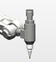
Figure 2-4: Graphic Track Tool
This creates a tool coordinate system, which can be named Toolpath. With the tip of the current tool as the origin and the extension direction of the tip as Z direction, the coordinate system conforms to the right-hand rule. Of course, after having the tool coordinate system, we need to set the tool coordinate coefficient data, which will be reflected in the RAPID program data. When setting coordinate coefficient data, the industrial robot should be placed in manual mode, and a fixed point should be found in its working range, where the fixed point is defined as a pin point on the tooling. Using the method of "TCP and Z" and 4-point calibration to create tool coordinate coefficient data, it can be named Path Tool. TCP data calibrated according to these four locations will be recorded by industrial robots and invoked in the program.
2.2.2 Tool and Tool Coordinate System for Glue Coating Track of Glass
Glass coating is a applications of trajectory control for industrial robots. The tool used is a rubber gun, as shown in Fig. 2-5. Since the rubber gun is also a tool with irregular shape, it is not possible to accurately calculate its offset relative to the initial tool coordinate system on the flange. So, it is important to re-establish the tool coordinate system and set relevant data for this workstation.
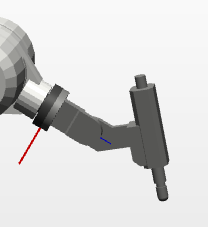
Figure 2-5: Glass Coating Track Tool.
In this workstation, in order to calibrate TCP more accurately, the six-point calibration method of "TCP and X/Z" will be used to teach and establish the tool coordinate system. Since this is a simulation of the application of the actual glass coating trajectory, some tool data parameters should be estimated before the tool coordinate system is established, as shown in Table 2-1. Specifically, the first four points are the TCP calibration points, and the last two are the extension points in their respective directions. Then use the teaching device to control the point of the rubber gun from different directions close to the fixed reference point for teaching.
Table 2-1: Data Parameters of Gun Tools
Name | numerical value |
Whether the Robot Holds Tools | Yes |
TCP directionsl offset along tool coordinate system | |
X | 29.009mm |
Y | 3.4589mm |
Z | 158.396mm |
Deviation of center of gravity along all directions of tool coordinate system | |
X | 1mm |
Y | 0 |
Z | 1mm |
Tool quality | 1kg |
2.3 Selection and Demonstration of Work piece Scheme
Work pieces are the objects of industrial robots. The correct establishment of work piece coordinate system is the basis of all programming, but also the preparation work that must be done before programming, so we need to build a work piece coordinate on the object, and then program on the basis of work piece coordinate. In essence, robot programming is to teach and create paths and target points in work piece coordinate system. In the trajectory application of industrial robots, the work piece coordinate system is particularly important because of the need to teach a large number of target points. In this way, even if the overall position of the work piece changes, it only needs to change the work piece coordinate system, and then update the program, without rewriting the program.
2.3.1 Work piece with graphical trajectory and its work piece coordinate system
In this part of the task, the coordinate system should be set up according to the actual position of the work piece, which is very convenient and fast for subsequent programming and operation. Firstly, we need to create a work piece coordinate system in the manual operation mode, which can be named WobjPath, and then use the common user three-point method to teach and calibrate the work piece coordinate system. The three locating points on the tooling are used to manually calibrate the three points X1, X2 and Y1 needed in the coordinate system of work piece graphics trajectory. The work piece coordinate system is shown in Figure. 2-6.
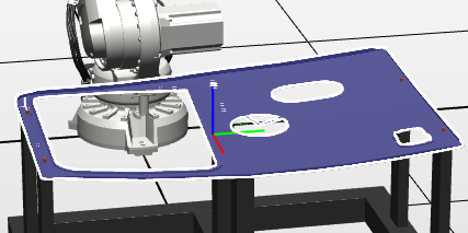
Figure 2-6: Graphic trace workpiece and coordinate system.
2.3.2 Work piece with Glue Coating Track and Its Work piece Coordinate System
In this glass gluing trajectory workstation, the coordinate system of the work piece is also calibrated by three-point method. The work piece coordinate system can be named WobjGlue as shown in Figure 2-7 below. Of course, before establishing the coordinate system, you can hide the glass that needs to be glued to prevent obstruction of sight. Because it simulates the application of glue coating in a highly real industrial field, when calibrating the work piece coordinate system, it is necessary to select the XY direction reasonably, so as to ensure that the Z axis direction is convenient for subsequent teaching and programming. The X, Y and Z axes conform to Cartesian coordinate system, which can also be determined by the right-hand rule. After calibrating the relevant points, the glass to be glued can be set as visible mode.
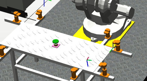
Figure 2-7: Gelatin Track Work piece and Its Coordinate System.
2.4 Programming Language Scheme Selection and Demonstration
There are many programming languages commonly used in industrial robots, but for ABB industrial robots, RAPID programming language is the most commonly used programming language.
As we all know, RAPID program is a special control language for ABB industrial robots. Because of its simplicity and more opportunities, ABB robots are broadly used. The RAPID program is the most suitable one to write the motion trajectory control program. Because it is also a kind of structured programming language close to the advanced level, and it can automatically generate the required program through the teaching programming target point, which is convenient for transplantation. It is suitable for the diversified programming needs of this design. In addition, it can also write programs without relying on specific hardware and through related software, which is more convenient to achieve. This is also conducive to the subsequent modification and debugging of the established trajectory motion program, thereby reducing unnecessary trouble and improving programming efficiency.
Chapter III. Design and Selection of System Hardware
3.1 Total Hardware Composition of the System
The two main tasks of this project are the IRB4600 used to design the graphic trajectory and the IRB1410 used to design the trajectory of glass coating. These two robots are widely used and play an important role in the family of ABB robots, especially IRB1410, which often appears in the fields of arc welding, gluing and handling. In this paper, the selection and introduction of the two robots and their hardware are given, and the selection of the I/O communication boards and the design of control signals are also carried out. Figure 3-1 below (schematic diagram of the overall control system)
Robot Ontology
IRC controller
Standard I/O Communication Board
Teaching device
Peripheral
Figure 3-1: Overall Control System Framework
3.2 Hardware of Graphic Trajectory Control System
In this workstation, the ABB-IRB4600 robot control system will be used to generate and control several graphic trajectories. It includes robot body, controller IRC5, teaching device and standard I/O communication board DSQC651.
3.2.1 IRB4600 Robot
The physical and working scope of IRB4600 ontology is shown in Figures 3-2 and 3-3 below. It is ABB's first industrial robot with enhanced and innovative functions and relatively compact fuselage. Mainly used in transportation, laser cutting, die casting and other fields. The machine adopts optimum design and has excellent adaptability to target application. The delicate fuselage makes the layout of production units more compact, realizes the double improvement of production capacity and quality, and promotes the production efficiency to a new level.
- Main characteristics
- Very high accuracy, probably the most similar products.
- The short cycle and fast trajectory operation benefit from the programming mechanism of "what is compiled and what is obtained".
- The work scope is large and the distance to be reached is long. Can meet a variety of demanding mission requirements.
- The fuselage is slim and covers a small area.
- The protection is well-equipped to effectively make sure the own security.
- It has strong applicability and can meet all kinds of harsh working environment and meet the demand.
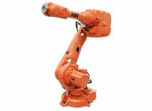
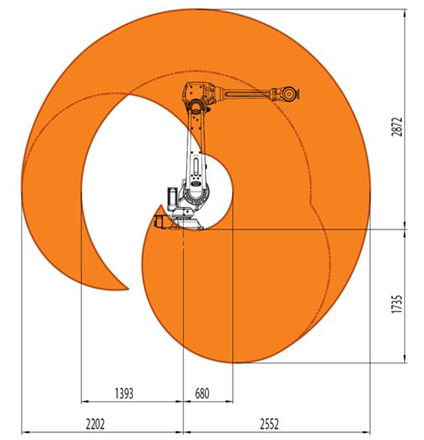
Figure 3-2: IRB4600 Ontology Figure 3-3: IRB4600 Work Scope
- Main parameters and performance
Table 3-1: Main parameters of IRB4600
Scope of work (reachable distance) | 2.05m |
Wrists | 40kg |
Relocation accuracy | 0.05mm |
Axle number | 6 axes |
3.2.2 IRC5 Compact Controller and Instructor
IRC5 is the fifth-generation controller of ABB industrial robot. The interior is mainly composed of control module and drive module. If you control multiple robots, you need a control module and connect multiple driving modules. In addition, it’s control accuracy and control flexibility are leading in the world. The object is shown in Figure 3-3 below. It has USB interface and network interface, and some bus interface, which can connect various standard I/O communication boards. Free transmission of program and rea on time on-line simulation can be realized. The internal servo drive system is shown in Fig.
Transformer
Rectifier
Gearbox
Axle computer
Master computer
Serial port measuring board
Driving plate
Electric machin
Encoder
Figure 3-4: Servo Drive System
As for the teaching device, it provides a human-machine interface for users to operate industrial robots. The user can manually manipulate the robot to move joints, write programs, debug the running trajectory program, and generate the Screen Maker monitoring interface.
3.2.3 DSQC651 Communication Board
In this task, I/O signals are less needed, and only a digital output signal is needed as a tool action signal. I/O module unit is set before I/O signal is set. The communication board selected in this part is standard I/O communication board DSQC651, which has eight digital input and eight digital output signals as well as two analog output signals. The default address of the board is 10, and the first digital output port of the board is used as the control signal of the tool, doLaserOn. The attributes corresponding to DSQC651 are shown in Table below.
Table 3-3: Corresponding Properties of Control Signal doLaserOn.
Name | Signal type | Distribution of equipment | Address assignment |
doLaserOn | Digital output | Board 10 | 32 |
3.3 Hardware of Track Control System for Glass Glue Coating
In this task, the robot used is ABB-IRB1410. Its control system will be used to generate and control the trajectory of a piece of glass coating. It includes the robot body, the controller IRC5 (the same as the controller used in the above graphic trajectory), the demonstrator and the standard I/O communication board DSQC652 used by the demonstrator.
3.3.1 IRB1410 Robot
This industrial robot is more familiar and welcomed in the production site. The main application fields are glue loading, sealing, arc welding and other trajectory applications. The robot body and its working range are shown in Fig below.
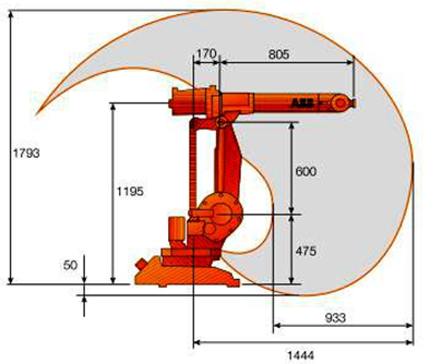
Figure 3-4: IRB1410 Ontology and its scope of work.
- Main characteristics
- Its process speed and location can be adjusted to achieve the best manufacturing accuracy, and the rate of defective products is very low, which is conducive to improving production efficiency.
- Low noise level, long maintenance cycle and long life. High return on investment in production and manufacturing.
- The work scope is relatively large, the structure is compact, the cost-effective ratio is high, and its wrist is slender. It is very suitable for arc welding, glue coating and other fields, even in demanding field, it can achieve high-performance operation.
- Main parameters and performance
Table 3-5: Main parameters of IRB1410
Scope of work | 1.44m |
Load-bearing capacity | 5kg |
Relocation accuracy | 0.05mm |
Axle number | 6Axis |
Maximum TCP Speed | 2.1m/s |
3.3.2 DSQC652 Communication Board
DSQC652 communication board is an upgraded version of predecessor 651. It expands the number of digital input and output signals to 16, so that more external control signals can be defined. In this task, this communication card is selected to configure the relevant I/O parameters. The I/O unit parameters of its configuration are shown in Table below.
Table 3-6: Configuration of I/O Unit Parameters.
Name | Unit type | Connected Bus | Address |
Board 10 | DSQC652 | DeviceNet1 | 10 |
In the design of this system, we need to configure a digital output signal doGlue to control the motion of rubber gun. A digital input signal diGlueStart is also needed to control the glue start signal. The assigned signal parameters are as follows:
Table 3-7: Distribution of Control Signal Parameters.
Name | Signal type | Allocated Equipment | Address Allocation |
doGlue | Digital output | Board 10 | 0 |
diGlueStart | Digital input | Board 10 | 0 |
Chapter IV. Design of System Software
Hardware is just the skeleton, and software is the heart of this design. We need to get done good work and proper plan to get the perfect result. Even when the software program has a little problem, it may lead to the whole design can’t work properly or even design failure.
In this topic, the main task of this part is to write a complete language program supported by industrial robots, so that it can complete the corresponding trajectory functions and requirements.
After compiling the RAPID language program supported by ABB industrial robot, the software design of the system runs on the given trajectory, and then completes the relevant debugging of software and hardware, so that the system can work normally and meet the predetermined functional requirements.
4.1 Robot Studio Software platform
Robot Studio is the most commonly used tool for the design and development of ABB industrial robot trajectory. It can not only import all types of ABB industrial robots and various user tools, but also customize user tools and work pieces through modeling. In addition, the platform can also realize the connection of virtual controller, import the teaching device and debug the related simulation and program. Of course, it can also connect to the real robot through the wire and import the program and related parameters for on-site debugging and analysis.
So, the design of software and hardware involved in this paper is implemented on this platform, including the construction of hardware platform, the teaching and writing of software program, the final debugging simulation and the overall operation.
4.2 RAPID Programming Language
RAPID programming language is a programming language developed by ABB for its industrial robots. It is a kind of language similar to VB, programming way is a little like MCGS configuration software, but the function is relatively more. It consists of program module and system module. The system module is usually written by the manufacturer, and what the user needs to write is the program module. The program framework is shown below in the Fig-
……
Program
Program Module 1
System module
Program Module 2
Routine procedures
Routine procedures
Manufacturer Writing
Figure 4-1: RAPID program framework.
4.3 Programming Module Division and Design
At present, the most popular and practical programming method should be modular programming That is to say, the whole program to be compiled is divided into several program modules, and then the corresponding programs are compiled for these functional modules respectively. Finally, these functional modules are integrated into the general program by function call, so as to achieve all the functions required by the design. Its advantage is that it is convenient to modify, debug and check errors, and easy to expand the relevant functions and upgrade the software version, so as to meet the changing needs of customers in a timely manner.
4.3.1 Graphic Trajectory Programming
In this part, the trajectory program of several graphs is edited, including the U-shaped slot trajectory, circular trajectory and the programming of two irregular graphics trajectory programs. The way of writing is to use the teaching device of industrial robots for teaching programming, and add relevant control instructions to the teaching points to realize the compilation of graphic trajectory. First of all, the four graphic trajectory programs need to establish a program module, and then they are divided into four routine subroutines, namely, the four graphic trajectory programs. Programming mainly adopts teaching target point programming method. The path planning and target points of these four cutting graphs are shown in Fig
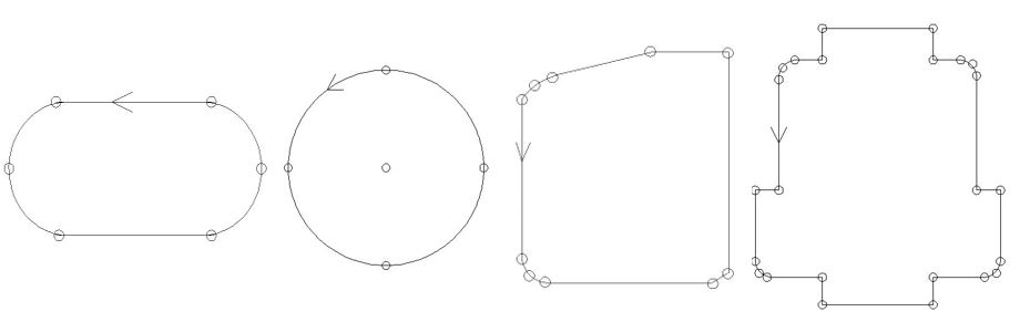
Figure 4-2: Graphic Path Planning and Target Points.
The specific process is as follows: first of all, it is necessary to determine whether the robot is at the mechanical origin, and if not, reset it back to the mechanical origin. Then, the cutting trajectories of U-shaped, circular and two irregular graphs are compiled in turn.
Here, the U-groove trajectory and circular trajectory are taken as examples to illustrate how to write this program (the coordinate system labeling is omitted here, the complete program is shown in Appendix 1)
IRB4600 Is it at the origin?
Begin
Back to the mechanical origin
UGroove shape
circular
Irregular figure 1
Irregular figure 2
Is it finished?
Back to the origin
End
Figure 4-3: Graphic Trajectory Program Flow Chart
1. U-groove trajectory program:
PROC Path1 ()
Move-I Offs (Path 1_10, 0, 0, 200), v2000, z20; Approximation Point of Trajectory
Move-L Path 1_10, v500, fine; starting point, speed set to 500, turning path fine, that is to say, need to stay, to ensure full access to this location.
Set doLaserOn; Positioning tool control signal
Move-L Path 1_20, v200, z5;
Move-C Path 1_30, Path 1_40, v200, z5; Arc instructions, smaller corner paths to ensure smooth trajectory operation
Move-L Path 1_50, v200, z5;
Move-C Path 1_60, Path 1_10, v200, fine;
Reset doLaserOn; Reset Tool Control Signal
Move-L Offs (Path 1_10, 0, 0, 200), v500, z20; locus departure point
ENDPROC.
2. Round trajectory program (only teaching the center of the circle, then using coordinate system offset to calculate four points on the circle, and using Move-C to complete the whole trajectory):
PROC Path2 ()
Move-J RelTool (Path 2_10, 100, 0, -200), v2000, z20; proximity point
Move-L RelTool (Path 2_10, 100, 0, 0), v500, fine; starting point
Set doLaserOn;
Move-C RelTool (Path 2_10, 0, -100, 0), RelTool (Path 2_10, -100, 0, 0), v200, z5;
MoveC RelTool (Path 2_10, 0, 100, 0), RelTool (Path 2_10, 100, 0, 0), v200, fine;
The arc instruction takes two offset points as the target point, and the last target point is the end point and the starting point.
Reset do LaserOn;
Move-L RelTool (Path 2_10, 100, 0, -200), v500, z20; departure point
ENDPROC.
4.3.2 Programming of Glue Coating Track for Glass
In this section, we will edit a RAID program for glass coating in combination with the industrial site. Unlike the method of on-line programming with the help of teaching aids for the graphic trajectory described above, Robot Studio offline programming method will be used in the glue coating trajectory program. That is, by directly adding paths and target points to the workstation and writing instructions. This programming method is more suitable for the actual production needs, and is now widely used in major industrial robots’ factories and mining enterprises. Because it can debug the program and simulate the effect without affecting the production, so as to improve the production efficiency and reduce the risk of hardware damage. Whether in industrial field or in teaching demonstration, tracing method is mostly used in trajectory programming. The industrial robot is switched to the require trajectory, and the position of each target point is recorded at one time. The number of target points will directly affect the trajectory accuracy. It may choose reasonably in conformity with the real trajectory. 39 target points are used in the glue coating trajectory designed in this paper. The problem that the curve around the glass is three-dimensional trajectory in space is solved by the method of splicing approximation of small straight lines and arcs.
No
Yes
NO
Yes
start
Back to the mechanical origin
Robot Initialization
IRB1410 Is it at the origin?
Whether the glue is started or not
Waiting
Execution of gluing procedures
Timer
Move the glue gun to the starting approach point
Starting position
Positioning glue gun signal
Gluing exercise
End position (start)
Reset glue gun signal
Move the rubber gun to its working position
Stop timing
Read clock values and reset
End
Figure 4-4: Procedure Flow Chart of Glue Coating Track for Glass
Whether in industrial field or in teaching demonstration, tracing method is mostly used in trajectory programming. The industrial robot is switched to the needed trajectory, and the position of each target point is recorded at one time. The number of target points will directly affect the trajectory accuracy It may choose reasonably in conformity with the real trajectory. 39 target points are used in the glue coating trajectory designed in this paper. The problem that the curve around the glass is three-dimensional trajectory in space is solved by the method of splicing approximation of small straight lines and arcs.
This part of the program framework is mainly composed of the main program, initialization program and gluing program (see Appendix 2 for the complete program). Firstly, the system needs to initialize the robot and check out how much the robot is working in its original position. If it is not working in its original position, if it is continuing to judge the starting signal of glue coating, if the starting signal is positioned, it will be glued and timed. When the glue gun moves to the beginning of the glue coating, the glue gun signal should be set to start spraying, and then the glue coating movement should be started. At the end of gluing, reset the glue gun signal and finish spraying. The robot leaves the glass to work in place and ends the time. Among them, the gluing program is the teaching programming of the target point, that is, the application of motion instructions. Among them, 31 linear motion instructions and 4 circular arc instructions are used to complete the teaching of the target points on all the trajectories. All the target points are shown in Fig. 4-5.
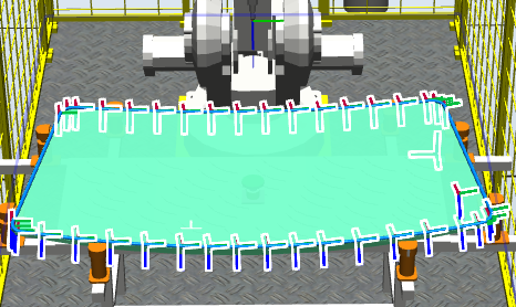
Fig. 4-5: Target Point of Glue Coating Trajectory
Here we introduce the design and initialization program.
- Main procedures:
PROC Main ()
RInitAll; Initializer is named to set the relevant attributes of the robot
WHILE TRUE DO This loop separates the robotic operating program from the initialization program
WaitDi diGlueStart, 1; Wait for glue signal to change to 1
RGlueProcess; Call the glue-coating program
ENDWHILE
ENDPROC
- Initialization program:
PROC rInitAll ()
VelSet 100,1000; the speed of program setting is 100%, the highest fastness limitation is 1000mm/s.
AccSet 70,70; Acceleration 70%, Acceleration gradient 70%, so that the robot starts and stop more gently
Reset doGlue; reset glue signal
MoveJ pHome, vMaxSpeed, fine; Position reset, the robot moves to the operation site
ClkStop GlueTimer; Stop Clock
ClkReset GlueTimer; reset clock
ENDPROC.
Chapter V. Trajectory Debugging and Operation
The normal operation of the design can only be known through repeated debugging and analysis. Debugging is divided into software debugging and hardware debugging. Software debugging is to write and debug programs on Robot Studio platform. Hardware debugging is to load the debugged program on the software platform into the corresponding industrial robot teaching device through the corresponding interface. The debugging function of the program can be used to debug and run conveniently. Then check whether the trajectory meets the requirements, and debug and verify the relevant functions. Because the actual site cannot meet the debugging requirements of this design, so we will debug it on Robot Studio platform. Although there is no specific on-site debugging, the proportion of the built objects on the platform is close to the site one to one.
5.1 debugging and operation of graphic trajectory
The program stops automatically after running once a week, and automatically starts running from scratch after running once continuously, i. e. circulating. Of course, in this task, the industrial robot completes the trajectory processing of the current work piece after running a program. The industrial robot needs to stop running, so it uses one-week mode to debug and run the trajectory. The specific debugging step is to debug the routine program of each graphic trajectory first, observe whether the trajectory runs in accordance with the requirements, and finally debug and run as a whole. Detailed screenshots of debugging and operation are shown below.
1. The debugging of U-groove trajectory is shown in Fig. 5-1 below.
The trajectory debugging of this part corresponds to the Path1 subroutine in the program. First, the PP is moved to the routine and Path1 is selected. Then the trajectory can be debugged. After debugging, the tool tip first reaches the approaching point of the U-shaped trajectory, then moves to the starting point of the trajectory and then moves to the starting point of the circular arc through a straight line. The circular arc motion is completed through the circular arc instruction. The final trajectory passes through the six target points taught in advance perfectly and smoothly completes the whole U-shaped trajectory.
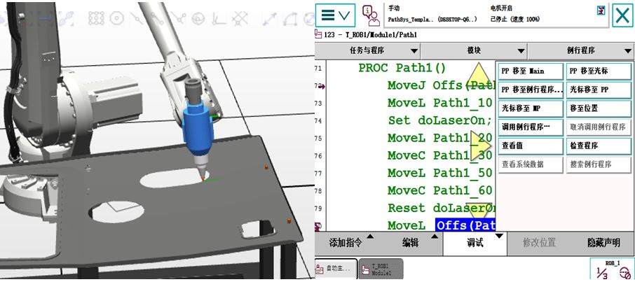
Figure. 5-1: U-groove trajectory debugging
2. The debugging of circular trajectory is shown in Fig. 5-2 below.
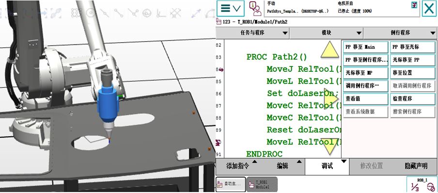
Fig. 5-2: Round Trajectory Debugging
The trajectory debugging of this part corresponds to the Path 2 subroutine in the program. Move PP to the routine and select Path 2. Then the trajectory can be debugged. Since this part of the trajectory programming is based on the center of the circle as the reference point and uses the migration function to calculate four uniformly distributed migration points on the circle, the key point in debugging is whether the trajectory reaches the four target points accurately. After debugging, the tool tip first reaches the approaching point of the circular trajectory, and then reaches the four preset offset points on the circle through two arc commands, including the departure point or the starting point.
- The debugging of irregular trajectory figure 1.
The trajectory debugging of this part corresponds to the Path 3 subroutine in the program. Move PP to the routine program and select Path 3. Then the trajectory can be debugged. After debugging, the tool tip first reaches the approaching point of the graphics trajectory, then through the teaching target point (mainly corner or turning point) and finally completes the graphics operation.
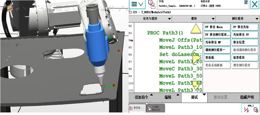
Figure. 5-3: Track Debugging of Irregular figure-1
4. The debugging of the trajectory of irregular figure 2.
The trajectory debugging of this part corresponds to the Path 4 subroutine in the program. Move PP to the routine and select Path 4. Then the trajectory can be debugged. After debugging, the tool tip first reaches the approaching point of the graphic trajectory, then the straight line movement reaches the starting point of the circular arc, completes the circular arc movement through the circular arc instruction, then reaches the corner of the broken line through the straight line movement, and then passes through the turning point in turn, finally returns to the starting point through a circular corner, and ends the operation of the graphic trajectory.
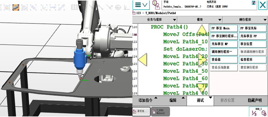
Figure 5-4: Track Debugging of Irregular Figure 2
5. The debugging of the overall trajectory is shown in Fig. 5-5 below.
The trajectory debugging of this part corresponds to Maine main program in the program. Move PP to routine program and select Main. Then the whole trajectory can be debugged by determining the trajectory. When debugging the whole system, one-week mode is chosen, and the percentage of running speed is changed to 25% for the first debugging, and 100% for the first time after confirming that there is no problem. After debugging, the tool tip completes the smooth operation of U-shaped trajectory, circular trajectory and the trajectory of two irregular figures in turn, and finally returns to HOME point.
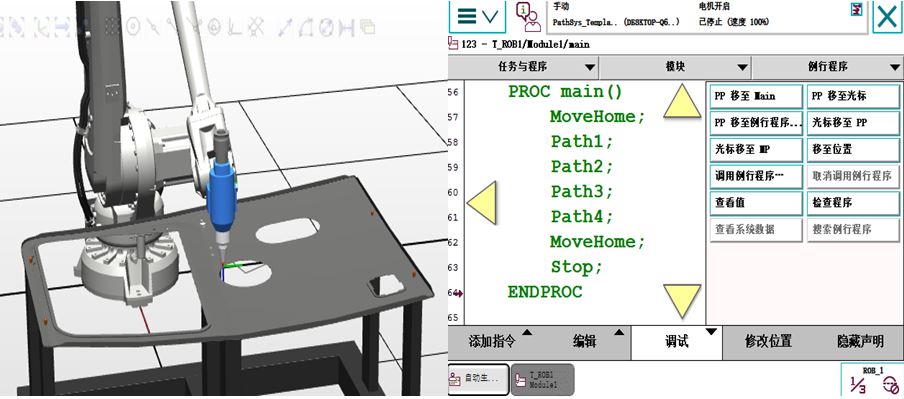
Figure. 5-5: Overall Trajectories Running and Debugging.
5.2 Adjustment and Operation of Glass Coating Track
Because this design simulates the real application in the industrial field, the continuous mode is used for debugging instead of the one-week mode used for the above graphic trajectory. Since I/O signals are added to the program for logical judgment, the next trajectory processing is automatically started after the replacement of the work piece, i.e. glass, is determined.
When debugging, because a glue start signal is set in the task, the robot did not perform the action at the beginning. This is to simulate that before the start of gluing, it is necessary to confirm manually whether the glass to be processed has been fixed in place, and then the gluing trajectory can be executed. This startup signal is preset in the workstation, similar to the glue startup button set in the workstation. Here, the glue start signal can be positioned in the "I/O simulator" during the simulation. The diagram of debugging and operation is given under in the photo.
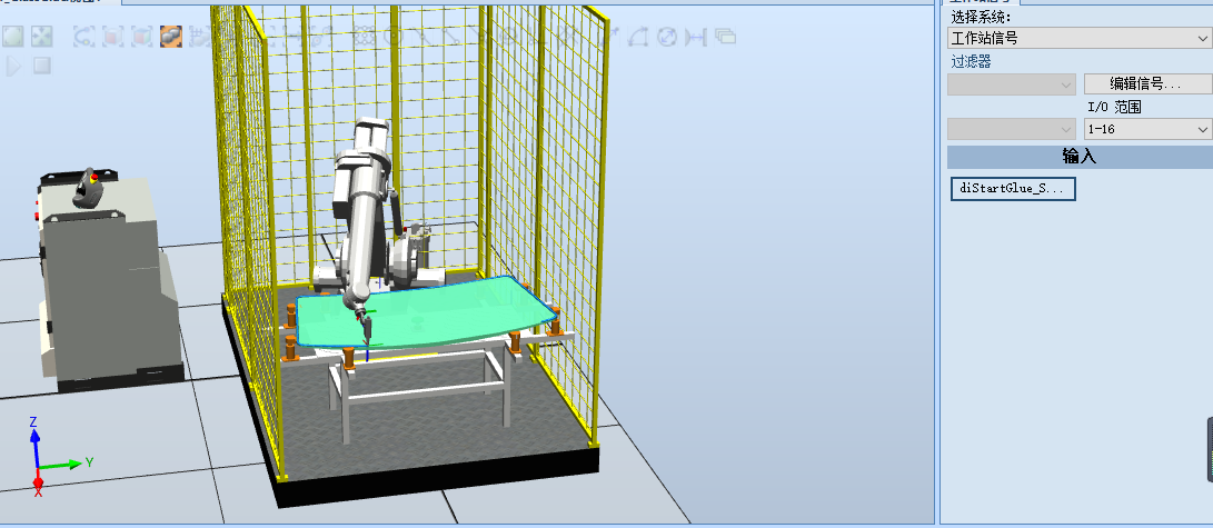
Figure. 5-6: Debugging and Operation of Glue Coating Track for Glass.
After debugging, the robot first moves rapidly from the working position to the near position of the beginning of the glue coating, then moves at a medium speed to the starting position of the glue coating, and then locates the glue signal and starts the running of the glue coating trajectory. There are 39 target points in the whole trajectory. Linear motion and arc motion are combined to complete the whole trajectory. the starting point, the glue gun signal is reset and the glue coating is stopped. Of course, after gluing, the robot moves quickly to the top of the gluing end point and eventually returns to its original position.
After running, the system will display the time of the last coating, click on the start signal again, and the system will automatically carry out the next coating. As shown in Figure 5-7 below.
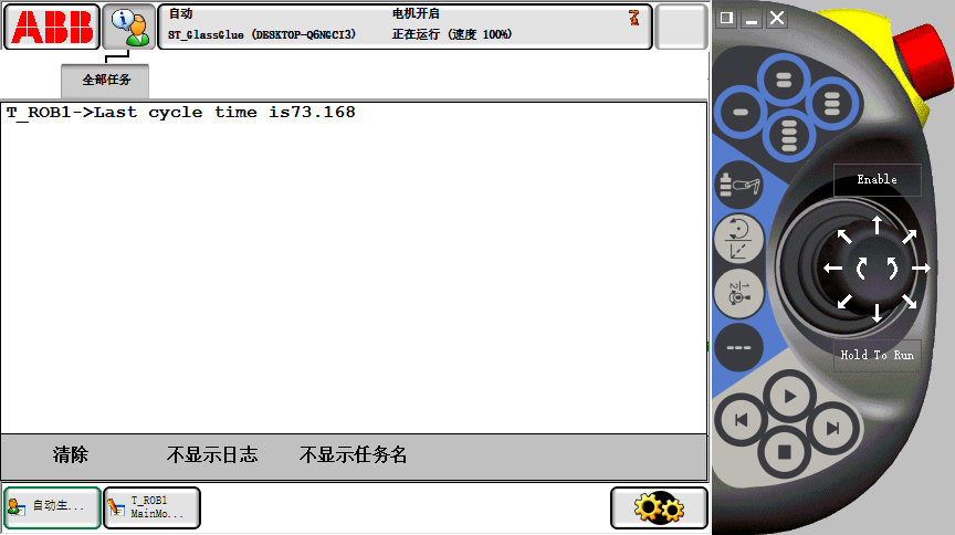
Figure 5-7: Display of Gluing Time.
Chapter VI. Summary and prospect
6.1 Summary
This graduation project completed the control design and simulation task of six-joint industrial robot's trajectory based on ABB, and programmed language and software design with RAPID language, which is the most commonly used language on the platform. After repeated debugging and testing of software and hardware, it can basically meet the goals and functional requirements formulated at the beginning of the design, and can complete all the basic functions and scheduled functions.
Specifically, two tasks are realized: graphic cutting track and glass gluing track. Then, I/O signals are configured with two different standard I/O communication boards. Then the most important software program design work is carried out. In this part, we mainly use the teaching programming method of target points to write programs with the help of RAPID programming language which is special for ABB. Finally, the whole program is debugged until the trajectory runs perfectly.
Of course, in the process of doing this graduation project, I also encountered many unexpected problems and troubles. However, these difficulties did not prevent me from continuing to study and study hard, but let me actively try all means to solve the problem and meet the difficulties. Eventually, with the help of teachers and classmates, all kinds of difficult problems were solved and the design was completed.
Through constant discovery, solution and analysis of problems, my abilities in all aspects have been fully exercised. Through this design, I have gained good experience in the ability to accept new knowledge, self-study ability and project development and design ability, which laid a good foundation for future work.
6.2 Prospect
In this design, due to the relationship between time and academic level, there may be some compromises on the perfect realization of some designs, and some technologies need to be further studied and deepened. There are mainly the following points-
- The robot cannot be controlled intelligently by some intelligent sensors. If a visual recognition system is added, the work piece can be automatically identified and positioned for the operation of the graphic cutting trajectory.
- The trajectory of motion is somewhat single and lacks diversification.
- Glue-coated glass needs to be replaced manually and the start signal of glue-coated glass needs to be turned on. If only the glass can be replaced automatically. For example, visual aided system is added to realize the automatic recognition of processed glass and the recognition signal is used as the starting signal of gluing, so that the process of gluing is completely unmanned.
Till now whatever I have write down and explained is not very good enough. I have tried my best to conquer my knowledge from the source below and some of them from reading books during my bachelor study and from my supervisor and fulfill this paper/thesis.I believe that through my further study, we will eventually find a perfect solution.
Reference
[1] Zhang Mingwen. ABB Six-axis Robot Introduction Practical Course [M]. Harbin University of Technology Press, 2017.01. ISBN 978-7-5603-6443-8
[2] Wei Zhili, Lin Yanwen. Industrial Robot Application Foundation - ABB Robot [M]. Beijing University of Aeronautics and Astronautics Press. 2016.11. ISBN 978-7-5124-2169-1
[3] Liu Peng. Development and Trend of Industrial Robots in China [J]. Robot Technology and Applications, 2012 (05): 20-22.
[4] Lin Wei.ABB: Industrial Robot Race for the 4.0 Era [J]. State Grid, 2015 (08): 64-67
[5] Meng Minghui, Zhou Chuande, Chen Libin, Feng Zhao, Miao Chunzhen. Overview of Ramp;amp;D and application of industrial robots [J]. Journal of Shanghai Jiaotong University, 2016,50 (S1): 98-101
[6] Lihui Wang. Robotics and Computer-Integrated Manufacturing [J]. Robotics and Computer Integrated Manufacturing, 2018,51.
[7] Robot needle-punching for manufacturing composite preforms [J]. Xiaoming Chen, Yufen Zhao, Chunyan Zhang, Xiaoxu Wang, Li Chen. Robotics and Computer Integrated Manufacturing, 2018,50.
[8] Wang Liyu, Cao Qixin, Dong Zhong. Design of Industrial Robot Control System Based on EtherCAT Bus [J]. Combination Machine Tool and Automation Machining Technology, 2017 (10): 74-76 81
[9]. Research and development of six-axis industrial robot control system based on EtherCAT bus [D]. Su Bingen ,South China University of Technology, 2013
[10] Design of Industrial Robot Control System Based on CAN Open [J]. Instrument Technology, 2011 Xue Zhengqing, Wang Jian, Guo Chongbin, Zhaoyang. (01): 47-48 56.
[11] Liangyuan, Luo Qingsheng, Shilin, Suhaixin. Application of CAN Bus Technology in Control System of Industrial Palletizing Robot [J]. Today Electronics, 2009 (06): 54-55
[12] Design of Asynchronous Serial Communication Relay System for Zhang Yang, Huang Kecheng, Liu Ning. ABB Robot [J]. Southern Agricultural Machinery, 2015, 46 (07): 22-23
[13] Application of serial communication between industrial PC and single chip computer in welding robot for die and mould [J]. Cui Xingqiang, Wang Hufu, Wu Jun. Mechanical and electrical engineering technology, 2005 (02)
[14] Lihui Wang. Robotics and Computer-Integrated Manufacturing [J]. Robotics and Computer Integrated Manufacturing, 2018,51.
[15] Zhu Lin, Wu Haibo. Industrial Robot Simulation and Offline Programming [M]. Beijing University of Technology Press. 2017. ISBN 978-7-5682-4351-3
[16] Wei Hongming. Design of ABB Industrial Robot Arc Welding Workstation Based on DeviceNet [J]. Machinery, 2013, 40 (03): 23-27
[17] Richard Meyes, Hasan Tercan, Simon Roggendorf, Thomas Thiele, Christian Byuscher, Ma
rkus Obdenbusch, Christian Brecher, Sabina Jeschke, Tobias Meisen. Motion Planning for Industrial Robots using Reinforcement Learning [J]. Procedia CIRP, 2017, 63.
[18] Ye Hui et al. Industrial Robot Practice and Application Skills [M]. Machinery Industry Press, 2017.9. ISBN 978-7-111-57493-4
[19] Ye Hui et al. Industrial Robot Industry Application Training Course [M]. Machinery Industry Press, 201.5. ISBN 978-7-111-51293-6
[20] Wang Dongdian, Zhu Xunlin. Industrial Robot Technology and Application [M]. China Electric Power Publishing House, 2016.ISBN 978-7-512-30706-5
[21] Wang Ting. Design and implementation of seam tracking and automatic gluing system for industrial robots [D]. Beijing University of Technology, 2015
[22] Li Shuangshuang. Modeling, motion simulation and trajectory optimization of industrial robots [D]. Inner Mongolia University, 2012
[23] Song Zhipeng. Realizing Automatic Coding Task Based on ABB Industrial Robot IRB1410 [J]. New Technologies and Products of China, 2017, (05):9
[24] Zhu Honglei, Daihui, Tianyuan Garden, Lin Yanfei. Design and Implementation of Multi-functional Workstation Based on ABB IRB120 Industrial Robot [J]. Mechatronics Information, 2016 (36): 126-127
[25] Nwokomah Wilson Gosim, Tarig Faisal, H.M.A.A. Al-Assadi, Mahmud Iwan. Pick and Place ABB Working with a Liner Follower Robot [J]. Procedia Engineering, 2012, 41.
[26] Energy Efficient Trajectories for an Industrial ABB Robot [J]. Procedia CIRP, 2014, 15
[27] Zhu Honglei, Daihui, Tianyuan Garden, Lin Yanfei. Design and Implementation of Multifunctional Workstation Based on ABB IRB120 Industrial Robot [J]. Mechatronics Information, 2016 (36): 126-127
[28] Sui Xin. Teaching Design of ABB Industrial Robot Simulation Based on Robot Studio [J]. Modern Business Industry, 2016, 37 (31): 167-168
Thankfully
First of all, I would like to thanks professor Mr. Shu Zhi Bing my supervisor and his students my senior Mr. Maxwell (chen xuezhang). Sir, without both of your guidance and support I would not have written this thesis. I'm grateful for your wonderful support during the period of time I have been working on my project. It was very encouraging and intensive security to make my dissertation preventable.
I have had wonderful support from my parents. My heartiest love to my father and mother for the time and mental support they lent me during the study period and particularly writing the dissertation. So, I would like to dedicate the success of finishing this study to them.
I not only acquired sufficient academic knowledge and enhanced operational ability, but also to a certain extent understood the research situation and development prospects in the field of industrial robots, and also harvested a lot of unexpected wealth of life, all of which will lay a solid foundation for my further study and learning in the future. In addition, in the design, I also encountered a lot of programming and debugging questions, but ultimately under the guidance of the tutor's patience, with the enthusiastic help of classmates and friends to be solved. Most importantly, from the teacher's usual guiding ideology, I learned a lot of philosophical ideas to solve problems, which benefited me for life.
At the end thanks to those of my wonderful classmates and friends who have always supported me with positive motivation and necessary supports.
Appendix A: Graphic Track Program
MODULE Module1
PROC main ()
MoveHome;
Path1;
Path2;
Path3;
Path4;
MoveHome;
Stop;
ENDPROC
PROC MoveHome()
Reset doLaserOn;
MoveJ pHome,v1000,fine,tCutTool\WObj:=WobjDoor;
ENDPROC
PROC Path1()
MoveJ Offs(Path1_10,0,0,200),v2000,z20,tCutTool\WObj:=WobjDoor;
MoveL Path1_10,v500,fine,tCutTool\WObj:=WobjDoor;
Set doLaserOn;
MoveL Path1_20,v200,z5,tCutTool\WObj:=WobjDoor;
MoveC Path1_30,Path1_40,v200,z5,tCutTool\WObj:=WobjDoor;
MoveL Path1_50,v200,z5,tCutTool\WObj:=WobjDoor;
MoveC Path1_60,Path1_10,v200,fine,tCutTool\WObj:=WobjDoor;
Reset doLaserOn;
MoveL Offs(Path1_10,0,0,200),v500,z20,tCutTool\WObj:=WobjDoor;
ENDPROC
PROC Path2()
MoveJ RelTool(Path2_10,100,0,-200),v2000,z20,tCutTool\WObj:=WobjDoor;
MoveL RelTool(Path2_10,100,0,0),v500,fine,tCutTool\WObj:=WobjDoor;
Set doLaserOn;
MoveC RelTool(Path2_10,0,-100,0),RelTool(Path2_10,-100,0,0),v200,z5,tCutTool\WObj:=WobjDoor;
MoveC RelTool(Path2_10,0,100,0),RelTool(Path2_10,100,0,0),v200,fine,tCutTool\WObj:=WobjDoor;
Reset doLaserOn;
MoveL RelTool(Path2_10,100,0,-200),v500,z20,tCutTool\WObj:=WobjDoor;
ENDPROC
PROC Path3()
MoveJ Offs(Path3_10,0,0,200),v2000,z20,tCutTool\WObj:=WobjDoor;
MoveL Path3_10,v500,fine,tCutTool\WObj:=WobjDoor;
Set doLaserOn;
MoveL Path3_20,v200,z5,tCutTool\WObj:=WobjDoor;
MoveC Path3_30,Path3_40,v200,z5,tCutTool\WObj:=WobjDoor;
MoveL Path3_50,v200,z5,tCutTool\WObj:=WobjDoor;
MoveL Path3_60,v200,z5,tCutTool\WObj:=WobjDoor;
MoveL Path3_70,v200,z5,tCutTool\WObj:=WobjDoor;
MoveC Path3_80,Path3_90,v200,z5,tCutTool\WObj:=WobjDoor;
MoveL Path3_100,v200,z5,tCutTool\WObj:=WobjDoor;
MoveL Path3_110,v200,z5,tCutTool\WObj:=WobjDoor;
MoveL Path3_120,v200,z5,tCutTool\WObj:=WobjDoor;
MoveL Path3_130,v200,z5,tCutTool\WObj:=WobjDoor;
MoveL Path3_140,v200,z5,tCutTool\WObj:=WobjDoor;
MoveC Path3_150,Path3_160,v200,z5,tCutTool\WObj:=WobjDoor;
MoveL Path3_170,v200,z5,tCutTool\WObj:=WobjDoor;
MoveL Path3_180,v200,z5,tCutTool\WObj:=WobjDoor;
MoveL Path3_190,v200,z5,tCutTool\WObj:=WobjDoor;
MoveC Path3_200,Path3_210,v200,z5,tCutTool\WObj:=WobjDoor;
MoveL Path3_220,v200,z5,tCutTool\WObj:=WobjDoor;
MoveL Path3_230,v200,z5,tCutTool\WObj:=WobjDoor;
MoveL Path3_240,v200,fine,tCutTool\WObj:=WobjDoor;
Reset doLaserOn;
MoveL Offs(Path3_240,0,0,200),v500,z20,tCutTool\WObj:=WobjDoor;
ENDPROC
PROC Path4()
MoveJ Offs(Path4_10,0,0,200),v2000,z20,tCutTool\WObj:=WobjDoor;
MoveL Path4_10,v200,fine,tCutTool\WObj:=WobjDoor;
Set doLaserOn;
MoveL Path4_20,v200,z5,tCutTool\WObj:=WobjDoor;
MoveC Path4_30,Path4_40,v200,z5,tCutTool\WObj:=WobjDoor;
MoveL Path4_50,v200,z5,tCutTool\WObj:=WobjDoor;
MoveL Path4_60,v200,z5,tCutTool\WObj:=WobjDoor;
MoveL Path4_70,v200,z5,tCutTool\WObj:=WobjDoor;
MoveL Path4_80,v200,z5,tCutTool\WObj:=WobjDoor;
MoveL Path4_90,v200,z5,tCutTool\WObj:=WobjDoor;
MoveL Path4_100,v200,z5,tCutTool\WObj:=WobjDoor;
MoveL Path4_110,v200,z5,tCutTool\WObj:=WobjDoor;
MoveC Path4_120,Path4_130,v200,z5,tCutTool\WObj:=WobjDoor;
MoveL Path4_140,v200,fine,tCutTool\WObj:=WobjDoor;
Reset doLaserOn;
MoveL Offs(Path4_140,0,0,200),v500,z20,tCutTool\WObj:=WobjDoor;
ENDPROC
ENDMODULE
Appendix B: Glue Coating Track Procedure
MODULE MainMoudle
VAR clock GlueTimer;
PERS num CycleTime:=72.924;
PERS speeddata vMinSpeed:=[50,50,1000,5000];
PERS speeddata vMidSpeed:=[100,100,1000,5000];
PERS speeddata vMaxSpeed:=[500,250,1000,5000];
PROC Main()
rInitAll;
WHILE TRUE DO
WaitDi diGlueStart,1;
rGlueProcess;
ENDWHILE
ENDPROC
PROC rInitAll()
VelSet 100,1000;
AccSet 70,70;
Reset doGlue;
MoveJ pHome,vMaxSpeed,fine,tGlueGun\WObj:=wobj0;
ClkStop GlueTimer;
ClkReset GlueTimer;
ENDPROC
PROC rGlueProcess()
ClkStart GlueTimer;
MoveJ pApproach,vMaxSpeed,z10,tGlueGun\WObj:=wobjGlue;
MoveL pGlue_10,vMidSpeed,fine,tGlueGun\WObj:=wobjGlue;
Set doGlue;
MoveL pGlue_20,vMinSpeed,z5,tGlueGun\WObj:=wobjGlue;
MoveC pGlue_30,pGlue_40,vMinSpeed,z5,tGlueGun\WObj:=wobjGlue;
MoveL pGlue_50,vMinSpeed,z5,tGlueGun\WObj:=wobjGlue;
MoveL pGlue_60,vMinSpeed,z5,tGlueGun\WObj:=wobjGlue;
MoveC pGlue_70,pGlue_80,vMinSpeed,z5,tGlueGun\WObj:=wobjGlue;
MoveL pGlue_90,vMinSpeed,z5,tGlueGun\WObj:=wobjGlue;
MoveL pGlue_100,vMinSpeed,z5,tGlueGun\WObj:=wobjGlue;
MoveL pGlue_110,vMinSpeed,z5,tGlueGun\WObj:=wobjGlue;
MoveL pGlue_120,vMinSpeed,z5,tGlueGun\WObj:=wobjGlue;
MoveL pGlue_130,vMinSpeed,z5,tGlueGun\WObj:=wobjGlue;
MoveL pGlue_140,vMinSpeed,z5,tGlueGun\WObj:=wobjGlue;
MoveL pGlue_150,vMinSpeed,z5,tGlueGun\WObj:=wobjGlue;
MoveL pGlue_160,vMinSpeed,z5,tGlueGun\WObj:=wobjGlue;
MoveL pGlue_170,vMinSpeed,z5,tGlueGun\WObj:=wobjGlue;
MoveL pGlue_180,vMinSpeed,z5,tGlueGun\WObj:=wobjGlue;
MoveL pGlue_190,vMinSpeed,z5,tGlueGun\WObj:=wobjGlue;
MoveL pGlue_200,vMinSpeed,z5,tGlueGun\WObj:=wobjGlue;
MoveL pGlue_210,vMinSpeed,z5,tGlueGun\WObj:=wobjGlue;
MoveC pGlue_220,pGlue_230,vMinSpeed,z5,tGlueGun\WObj:=wobjGlue;
MoveL pGlue_240,vMinSpeed,z5,tGlueGun\WObj:=wobjGlue;
MoveC pGlue_250,pGlue_260,vMinSpeed,z5,tGlueGun\WObj:=wobjGlue;
MoveL pGlue_270,vMinSpeed,z5,tGlueGun\WObj:=wobjGlue;
MoveL pGlue_280,vMinSpeed,z5,tGlueGun\WObj:=wobjGlue;
MoveL pGlue_290,vMinSpeed,z5,tGlueGun\WObj:=wobjGlue;
MoveL pGlue_300,vMinSpeed,z5,tGlueGun\WObj:=wobjGlue;
MoveL pGlue_310,vMinSpeed,z5,tGlueGun\WObj:=wobjGlue;
MoveL pGlue_320,vMinSpeed,z5,tGlueGun\WObj:=wobjGlue;
MoveL pGlue_330,vMinSpeed,z5,tGlueGun\WObj:=wobjGlue;
MoveL pGlue_340,vMinSpeed,z5,tGlueGun\WObj:=wobjGlue;
MoveL pGlue_350,vMinSpeed,z5,tGlueGun\WObj:=wobjGlue;
MoveL pGlue_360,vMinSpeed,z5,tGlueGun\WObj:=wobjGlue;
MoveL pGlue_370,vMinSpeed,z5,tGlueGun\WObj:=wobjGlue;
MoveL pGlue_380,vMinSpeed,z5,tGlueGun\WObj:=wobjGlue;
MoveL pGlue_390,vMinSpeed,z5,tGlueGun\WObj:=wobjGlue;
MoveL pGlue_10,vMinSpeed,fine,tGlueGun\WObj:=wobjGlue;
Reset doGlue;
MoveL pDeparture,vMidSpeed,z10,tGlueGun\WObj:=wobjGlue;
MoveJ pHome,vMaxSpeed,fine,tGlueGun\WObj:=wobj0;
ClkStop GlueTimer;
CycleTime:=ClkRead(GlueTimer);
ClkReset GlueTimer;
TPErase;
TPWrite "Last cycle time is"\Num:=CycleTime;
ENDPROC
ENDMODULE
以上是毕业论文大纲或资料介绍,该课题完整毕业论文、开题报告、任务书、程序设计、图纸设计等资料请添加微信获取,微信号:bysjorg。
相关图片展示:


