基于单片机的三相中频航空电源设计外文翻译资料
2023-08-17 15:22:37
Design of Three-phase Intermediate Frequency Aviation Power Based on Single Chip Microcomputer
Abstract—A three-phase intermediate frequency aviation inverter power with single chip microcomputer and SA8282 as its main controller is designed in this paper. The overall structure of the proposed system is given. The working principle and design method of the main circuit are presented in detail. Among the control circuit design process, the generation of SPWM waveforms, the main parameters design of SA8282, the digital PI regulation and the software design process are analyzed. The proposed control strategy has been implemented on a 9KVA, 400Hz three-phase power supply. Experimental results show that the three-phase output voltage waveforms are quite good, the performance of the supply
meets the demand.
Keywords- inverter; single chip microcomputer(SCM); Intelligent Power Module (IPM); controller; Sinusoidal Pulse Width Modulation (SPWM)
I. INTRODUCTION
Compared with the traditional power equipment, inverter power system has the merit of high reliability, good stability, excellent regulation characteristics, small size, light weight and low power consumption. It has been widely used in electronics and electrical field. With the using of advanced power electronic devices and high-frequency inverter
technology, inverter power makes the traditional frequency rectifier materials reduced by 80% -90%, saves energy about 20%-30%, and the dynamic response speed increases 2-3 orders of magnitude. It develops in the direction of the high frequency-based, lightweight, modular, intelligent and largecapacity [1]. With the rapid development of power electronics and the improved control performance requirements of electrical equipment industries, inverter technology has been used for power supply and applied in many fields with increasingly demanding. Some electrical equipment in many industries are not directly provided by the AC power grid as a power supply, but through various transform of AC power to obtain the energy needed to form their own.
A number of important units and departments that need to use electricity, particularly aerospace and naval, have become increasingly demanding quality of supply, which need the voltage, frequency andwaveform accurate, dynamic performance perfectly, it can not be interfered by the grid, that means a clean or purification power supply conditions. 400Hz medium frequency inverter power supply system is widely used in aircraft, ships, radar, communications and vehicles throughout
the world as a standard power supply system [2][3]. This paper designs a 9KVA three-phase inverter power supply, which uses single chip
microcontroller 80C196KC and SA8282 to generate SPWM signals [4]. At the same time the intelligent power module (IPM) is selected to reduce the separation of discrete components and improve the output waveform quality and system reliability.
II. TOTAL DESIGN AND OPERATING PRINCIPLE
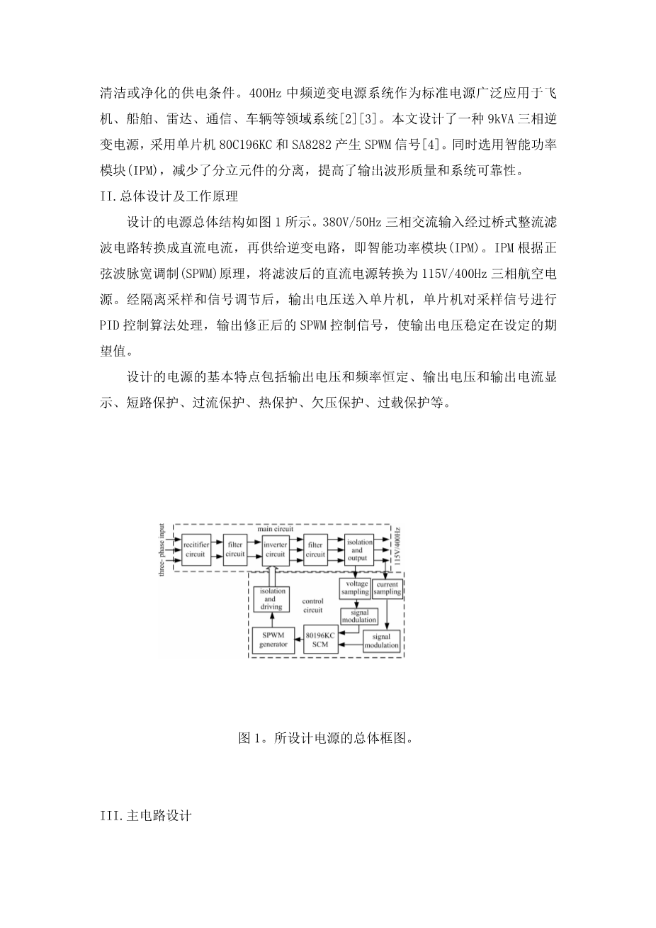
The overall structure of the designed power supply is shown in Fig.1. 380V/50Hz three-phase AC input is converted into DC power through the bridge rectifier and filter circuit, and then it supplies the inverter circuit, which is the intelligent power module (IPM). According to the
principle of sine-wave pulse-width modulation (SPWM), the IPM converts the filtered DC power into three-phase 115V/400Hz aviation power. After isolated sampling and signal regulation, the output voltage is sent into the SCM, the SCM handles the sampled signal with PID control algorithm
and outputs the amended SPWM control signals, so that the output voltage is stabilized at the set expectation value.
The basic features of the designed power include constant output voltage and frequency, the display of output voltage and output current, short circuit protection, over current protection, thermal protection, under-voltage protection, over-load protection and so on.
Figure 1. The overall block diagram of the designed power supply.
III. THE DESIGN OF MAIN CIRCUIT
The main circuit of designed power supply is shown in
Fig.2, which mainly consists of the following components.
Figure 2. The main circuit of the designed inverter.
A. Rectifier circuit
This paper uses three-phase bridge rectifier circuit, which is characterized by simple structure and high reliability.
B. Inverter Circuit
Inverter circuit is the IGBT Intelligent Module (IPM), which belongs to German SEMIKRON SKIIPPACK series. The IPM combines protection and output driver function as a whole, so the circuit is very simple to achieve. The use of the IPM avoids the previous shortcomings of discrete components, and makes the original complex conversion circuit become very light.
The intelligent IGBT module has a wide operating temperature range (-200 C~ 850 C), and also has over-current, over voltage and temperature protection functions, which is an excellent high-power IGBT. If the intelligent module is used in conjunction with Mitels SA8282, the converter will have good dynamic characteristic and static wave indicators.
C. Filter Circuit
The output of full-bridge inverter is a series of highfrequency pulse, we must filter out the high-frequency components to get the standard sine wave. So LC filter circuit can be selected to filter out the high frequency, which parameters of the LC filter are determined by resonant frequency and characteristic impedance.
D. Isolation and Transformer Circuit
In order to meet the requirements of the output voltage amplitude and electrical isolation between inverter input and output, a transformer is needed in the inverter power supply [2]. So a transformer is used in t
剩余内容已隐藏,支付完成后下载完整资料

英语译文共 10 页,剩余内容已隐藏,支付完成后下载完整资料
资料编号:[606086],资料为PDF文档或Word文档,PDF文档可免费转换为Word


