机器人快换抓手的设计毕业论文
2020-04-12 15:48:40
摘 要
随着目前工业机器人的广泛使用,在工厂实际生产过程中产生了要求快速更换末端执行器的需求。在文献调研过程中发现,现有的机器人快换抓手装置在使用过程中对于主盘与工具盘的锁紧是否可靠无法检测,这种情况下无法保证在工作过程中机器人与目标抓手之间连接可靠,以完成所需任务。
本文针对快换抓手装置的研究现状,同时对国内外现有的产品方案进行比较,通过对用户们的需求以及实际生产中出现的问题进行分析和研究,提出应用传感器等元件来增强可靠性的改进方案设计。对于设计过程中遇到的问题采用以下措施解决:
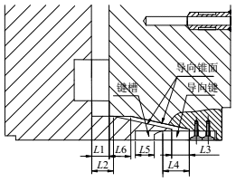
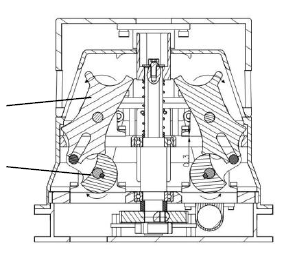
(1)采用活塞凸轮式夹紧方式。利用活塞杆的移动,锁紧凸轮与锁紧钢球之间发生刚性接触进行夹紧与释放。
(2)用气动传动提供动力。气缸输送的压缩空气控制主盘内腔活塞杆的移动,同时控制气动抓手的运动。
(3)采用西门子PLC进行控制。选择S7-1200PLC与触摸屏进行工作状态选择,PLC对电磁阀进行控制。
(4)运用传感器元件进行状态监测。选择接近开关放置在主盘内腔,监测活塞位置来监测夹紧状态。
此次设计要求完成机械快抓换手装置的整体设计。要求可以自动换取抓手,通用性强,可以应用在不同型号机器人手臂上。并可以承受负载20kg,并为了提高机构的可靠性,设计防故障锁紧设计。同时进行控制系统的程序设计,进行抓手加紧与释放的控制和抓手的气路控制。
此次设计内容对于快换装置的控制系统中的工作原理进行了详细解释,对于提高机械装置与电气装置综合使用,改善稳定可靠性,具有启示意义。传感器元件的使用提高了安全性与精度。同时,快换抓手装置的发展对于增强机器人作业柔性,提高机器人使用效率,降低企业生产成本具有重大意义。
关键词: 快换抓手;结构设计;力学分析;控制系统
Abstract
With the wide use of industrial robots, there is a demand for quick replacement of end-effector in the process of the factory production. In the process of literature research, I found that the existing robot quick-change of gripper system is unable to detect that whether it locks well. There is no guarantee that whether the robot is stable and reliable to pick up or replace different enforcement tools to accomplish the required task. This article studies the present situation of the research and compares the existing product scheme. At the same time, I analyze the problems existing in the process of using and put forward an improved scheme by applying sensor and other components to enhance the reliability of the quick change gripper system. The main contents of the paper are as follows:
(1)The clamping scheme of the quick change gripper device adopted piston CAM clamping. The cam and the locked ball generate the rigid contact to clamp and release by using the piston rod movement.
(2)The switching scheme of the quick change gripper system adopts pneumatic switching to provide power. The compressed air delivered by the cylinder controls the movement of the piston rod in the cavity of the main plate. It also controls the movement of the pneumatic gripper.
(3)The device that proposed in this paper adopts the Siemens PLC for control. We operate it by pressing the button of the touch screen to select the working state. Also I Select the S7-1200 PLC to control the electromagnetic valve to employ the gripper.
(4)Several sensor elements on the device are used to determine the working state. The proximity switches that were placed in the cavity of the main plate monitor the position of piston to notarize the clamping state.
The design requires the completion of the overall design of the quick change gripper device. It is required that can be automatically replaced with a gripper. It needs strong universality and can be applied to different types of robot arms. Besides it can bear a load of 20kg and has the fail-safe locking design to improve the reliability of the mechanism. Besides, the program design of the control system was carried out to control the tightening and releasing state and the air path control of the gripper.
The content of the paper explain in detail the operation principle of the control system of the device. The content of the design is of enlightenment significance to improve the stability and reliability and improve the comprehensive use of the machinery and electrical installation. The using of sensor elements is beneficial to improving the security and precision. At the same time, the development of quick-change gripper device is of great significance to improve the efficiency of robot operation, enhance the flexibility of robot operation and reduce the production cost of enterprises.
Key Words: Robotic tool changer; Structure design; Dynamic analysis; Assembly variation analysis
目录
摘要 I
第1章绪论 1
1.1研究背景 1
1.2目的及意义 1
1.3国内外现状 2
1.3.1国外快换装置的发展现状 2
1.3.2国内快换装置的发展现状 4
1.4研究内容 7
第2章工作原理及设计方案 8
2.1设计准则 8
2.2设计方案 8
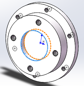
2.2.1夹紧方案选择 8
2.2.2切换方案选择 9
2.2.3工作原理 10
2.2.4改进方案 11
2.3技术参数 11
第3章结构设计 12
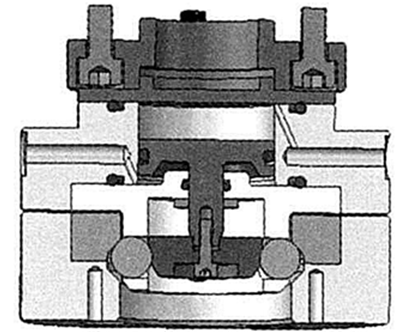
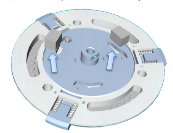
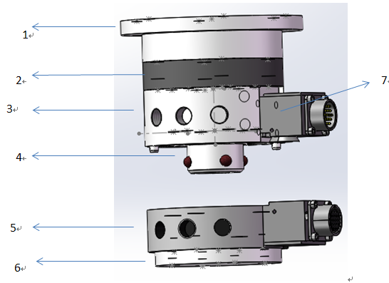
3.1基本组成 12
3.2机械设计 13
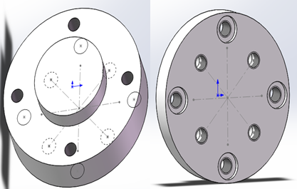
3.2.1主盘连接板 14
3.2.2主盘 15
3.2.3套筒 17
3.2.4锁紧环 18
3.2.5锁紧凸轮 19
3.2.6锁紧钢球 20
3.3气路设计 21
3.3.1气路模块介绍 21
3.3.2气路元件选择 23
第4章控制系统设计及仿真 28
4.1硬件选型 28
4.2功能要求 30
4.3软件设计 30
4.3.1自动加紧程序设计 31
4.3.2自动放松程序设计 32
4.3.3触摸屏操作程序设计 33
4.3.4加紧放松与抓手动作程序设计 35
4.3硬件原理图 36
第5章ANSYS力学分析 38
5.1应用软件模块介绍 38
5.2ANSYS分析过程 38
5.3仿真结果分析 39
5.3.1套筒分析结果 39
5.3.2锁紧环分析结果 41
第6章结论 44
6.1总结 44
以上是毕业论文大纲或资料介绍,该课题完整毕业论文、开题报告、任务书、程序设计、图纸设计等资料请添加微信获取,微信号:bysjorg。
相关图片展示: