某微车后副车架结构设计及性能分析毕业论文
2020-04-12 15:43:25
摘 要
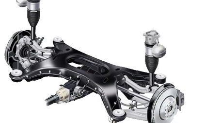
随着人们生活水平的提高和全球能源短缺问题的出现,汽车的改进研究已成为越来越重要的课题。后副车架作为汽车底盘重要的组成部件之一,支撑和传递着汽车在行驶过程中受到的各种载荷力,减小路面的振动传入,有效的提高了汽车操作性和乘坐舒适性,同时,后副车架将悬架散件形成总成,增加安装的便利性,提高悬架刚度,在汽车上的使用和普及具有重要的现实意义。
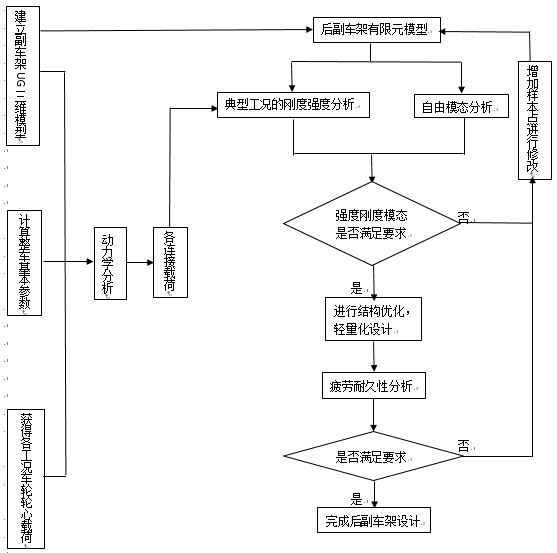
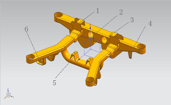
本文选用生活中常见的微车,完成了一款适用于该车型后副车架。首先根据车型的边界条件和约束,确定后副车架结构和形状,经过参数计算得到后副车架与悬架连接件的角度和结构尺寸,依次利用UG软件完成后副车架三维建模;然后对后副车架进行多体动力学分析,通过计算后轮受力大小,在ADMAS/car中模拟五种典型工况下汽车实际运转情况,获得后副车架各控制臂连接点的受力情况;再在ANSYS Workbench软件中,将建立好的后副车架三维模型导入,进行五种情况下的静力学分析和模态分析,根据分析结果,后副车架满足强度刚度的设计要求,位移改变量符合标准,并且未出现频率混叠和共振的现象;然后进行后副车架形状尺寸的优化,进行轻量化的设计,选择合适的优化参数,分析结果结构减重约4%,再根据优化结果完成对后副车架的结构和尺寸的改进,进行三维建模,将优化后后副车架进行有限元分析,优化后结构仍满足应力破坏和模态性能的要求,达到汽车减重的目的;最后进行疲劳分析,导入材料S-N曲线,在软件中进行仿真模拟,获知后副车架使用寿命值和疲劳破坏最容易损坏位置,该结构满足使用寿命的标准,同时为后续后副车架的安全使用及设计提供参考。
关键词:后副车架;静应力学分析;模态分析;轻量化设计;疲劳分析;ANSYS
Abstract
With the improvement of people’s living standards and the emergence of global energy shortages, the improvement of automobiles has become an increasingly important issue. The rear subframe is one of the important components of the chassis of the vehicle. It supports and transmits the various load forces that the car receives during the driving process, reduces the incoming vibration of the road surface, and effectively improves the operability and ride comfort of the vehicle. At the same time, the rear sub-frame will form an assembly of suspension parts, increasing the convenience of installation, improving the stiffness of the suspension, and its use and popularity in automobiles have important practical significance.
This article selects a micro-vehicle common in life and completes a sub-frame suitable for this model. First, according to the boundary conditions and constraints of the vehicle model, the structure and shape of the rear subframe are determined. The angles and structural dimensions of the rear subframe and suspension linkage are obtained through parameter calculation, and then the three-dimensional modeling of the rear subframe is performed using UG software in sequence. Then the multi-body dynamics analysis was performed on the rear subframe, and the actual operation of the vehicle under the five typical operating conditions was simulated in the ADMAS/car by calculating the force of the rear wheels, and the connection points of the control arms of the rear subframe were obtained. Force situation; In the ANSYS Workbench software, the three-dimensional model of the rear sub-frame is established, and the static analysis and modal analysis under five conditions are performed. According to the analysis result, the rear subframe meets the design requirements of strength and stiffness. The amount of displacement change is in line with the standard, and there is no phenomenon of frequency aliasing and resonance; then, the shape of the rear subframe is optimized, lightweight design is performed, and the appropriate optimization parameters are selected. The analysis results are about 4% weight loss. Then according to the optimization results, the rear sub-frame structure and dimensions are improved, three-dimensional modeling is performed, and the optimized rear sub-frame is subjected to finite element analysis. The structure still satisfies the requirements of stress damage and modal performance and achieves the purpose of vehicle weight reduction. Finally, it conducts fatigue analysis, imports the SN curve of the material, and simulates it in software. It is learned that the service life value and fatigue damage of the rear subframe are most likely to be damaged. Position, the structure meets the standard of service life, and provides reference for the subsequent safe use and design of the rear subframe.
Key Words:Rear subframe;Static stress analysis;Modal analysis;Lightweight design;Fatigue analysis;ANSYS
目 录
第1章 绪论 1
1.1 后副车架概述 1
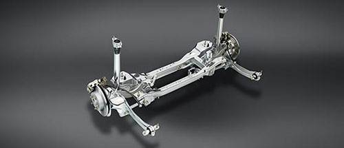
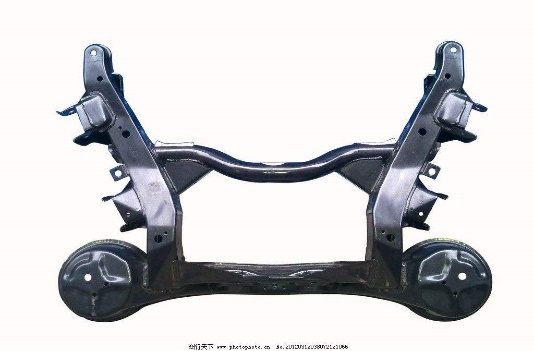
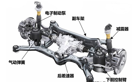
1.1.1 后副车架简介 1
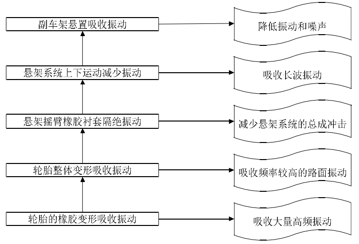
1.1.2 后副车架功能 2
1.1.3 后副车架分类 2
1.2 研究背景及目的 4
1.3 国内外研究现状 5
1.4 研究内容及研究手段 6
1.4.1 研究内容 6
1.4.2 研究手段 7
1.5 本章小结 8
第2章 后副车架的设计与三维建模 9
2.1 后副车架结构形式确定 9
2.2 后副车架相关参数的确定与计算 9
2.2.1 后副车架相关参数确定 9
2.2.2 后副车架相关参数计算 10
2.3 后副车架与悬架控制臂连接处角度计算 11
2.4 后副车架主要结构的尺寸确定 14
2.5 后副车架的三维建模 14
2.6 本章小结 15
第3章 后副车架多体动力学分析 16
3.1 多体动力学理论介绍 16
3.2 后副车架多体动力学运用 17
3.3 后副车架多种工况受力分析 17
3.3.1 后副车架实际工况分析 17
3.3.2 多种工况下后轮载荷计算 18
3.3.3 后副车架连接点在各工况下的载荷获取 20
3.4 本章小结 24
第4章 后副车架静应力学及模态分析 25
4.1 静应力学分析和模态分析介绍 25
4.1.1 静应力学分析理论简介 25
4.1.2 模态分析理论简介 26
4.2 后副车架有限元分析准备 26
4.2.1 模型的几何清理 26
4.2.2 材料定义与网格划分 26
4.3 后副车架静应力学分析 28
4.3.1 后副车架约束与连接点载荷的添加 28
以上是毕业论文大纲或资料介绍,该课题完整毕业论文、开题报告、任务书、程序设计、图纸设计等资料请添加微信获取,微信号:bysjorg。
相关图片展示: