Design of modular fixture for milling machine based on Solidworks毕业论文
2020-04-08 14:26:40
Design of modular fixture for milling machine based on Solidworks
学院(系): 机电工程学院
专业班级: 机自1201班
学生姓名: 夏 利
指导教师: 李 益 兵
学位论文原创性声明
本人郑重声明:所呈交的论文是本人在导师的指导下独立进行研究所取得的研究成果。除了文中特别加以标注引用的内容外,本论文不包括任何其他个人或集体已经发表或撰写的成果作品。本人完全意识到本声明的法律后果由本人承担。
作者签名:
年 月 日
学位论文版权使用授权书
本学位论文作者完全了解学校有关保障、使用学位论文的规定,同意学校保留并向有关学位论文管理部门或机构送交论文的复印件和电子版,允许论文被查阅和借阅。本人授权省级优秀学士论文评选机构将本学位论文的全部或部分内容编入有关数据进行检索,可以采用影印、缩印或扫描等复制手段保存和汇编本学位论文。
本学位论文属于1、保密囗,在 年解密后适用本授权书
2、不保密囗。
(请在以上相应方框内打“√”)
作者签名: 年 月 日
导师签名: 年 月 日
CONTEXTS
I Introduction 1
1.1 Purpose and Significance 1
1.2 Research Status and Development Trend of Combination Fixtures at Home and Abroad 3
1.2.1 Foreign Research Status 3
1.2.2 Domestic Research Status 3
1.2.3 Trends 4
1.3 Research (Design) Content 5
II. General knowledge about design of modular fixture 7
2.1 Fixture concept 7
2.2 The main function of the fixture 7
2.3 Classification of Fixtures 7
2.3.1 Universal fixture 7
2.3.2 Special fixture 8
2.3.3 Adjustable fixture 8
2.3.4 Combination fixture 8
2.3.5 Automatic line fixture 8
2.4 The composition of the fixture 8
2.4.1 Positioning support element 9
2.4.2 Clamping device 9
2.4.3 Connecting directional elements 9
2.4.4 Counter element or guide element 9
2.4.5 Other devices or components 9
2.4.6 Clip specific 9
2.5 Solidworks software 10
III. Design of Milling Clamp 12
3.1 Design Features of Milling Clamp 12
3.2 fixture clamping workpiece features 12
3.3 Milling Clamp Installation 13
3.4 The position of tool setting on the milling machine fixture 13
3.5 Initial Fixture Structure 13
3.6 the positioning program 14
3.6.1 Analysis of positioning plan 14
3.6.2 Workpiece positioning scheme 15
3.6.3 Clamping scheme 16
3.6.4 the determination of workpiece clamping program 18
3.7 cutter classification and selection 20
3.7.1 Classification according to the use of milling cutter 20
3.7.2 Classified by tooth shape of milling cutter 21
IV. Design Calculation 1
4.1 夹紧力计算 1
4.2 定位误差分析 1
4.3 定位误差分析 3
4.4铣削力的计算 4
4.5 Result of the design 5
V. Conclusion 6
Reference 7
Acknowledgement 8
I Introduction
1.1 Purpose and Significance
With the rapid development of the world economy and the increasingly fierce competition in the market, how to respond quickly to the needs of customers has become an important issue for modern manufacturing companies. Each manufacturer is doing its utmost to improve the competitiveness of the company by shortening the time to market for new products, improving product quality, and saving production costs.
It is known from relevant statistical data that at the present level of industry in our country, most of the time in a product development cycle is used for the design and manufacture of process equipment, and the focus of design and manufacture of process equipment lies in fixture design. Therefore, the design and manufacture of the fixture has a very important significance for the development of the product. The fixture is an important means to ensure the quality of the product. Therefore, in a sense, the level of design and manufacture of fixtures determines the competitiveness of a manufacturing company.
At present, the use of traditional machine tools has become less and less, in order to increase production efficiency, manufacturers have begun to use CNC machine tools for production, in order to meet the use of CNC machine tools, they are increasingly choosing a combination of jigs to carry out multiple varieties, small Mass production type of product production. The combination fixture has a wide variety of component libraries. The component library consists of pre-manufactured components and assemblies. Their structure and dimensions are different. They can be assembled with each other, with high precision and interchangeability and wear resistance. In use, a dedicated jig for the machining of the workpiece is assembled by selecting the desired combination jig element according to the contour and size of the workpiece to be processed. After use, these components are disassembled, and they can still be used to assemble assembly jigs for different workpieces in the next use.
However, due to the large variety of components, the large number of components, the relatively complex structure, and the relatively high manufacturing precision of the combined fixture, the traditional manual operation to design and assemble the combined fixture has many disadvantages, such as low design efficiency and cost. It takes a long time. The designer's experience has a great influence on design and assembly. It is difficult to identify the component interference problems that occur during assembly in advance, which results in an increase in the number of test assemblies. This not only greatly prolongs the cycle of the assembly fixture design. , And will make the combined fixture components wear faster, reducing the accuracy of the combination of fixtures. These shortcomings will eventually reduce the economic efficiency of enterprises and lose their competitiveness. In order to overcome these shortcomings, the use of computer-aided methods for the design of modular fixtures has received increasing attention.
The purpose of this project is to use existing resources to refer to the dimensional data and structural sketches of the drill jig assembly fixtures obtained from the laboratory survey and mapping, and to establish positioning components, clamping components, and supports for drilling jigs and fixtures in solidworks. The model of the component and other various components, build a component library, and then select the required component model for different machining parts to assemble and design the corresponding combined fixture solution. The significance of using solidworks to design a combined fixture scheme is that a combined fixture scheme can be designed more conveniently and quickly, which avoids the manpower and material resources that are required for on-site operation, minimizes the loss of fixture components, and improves the precision of the combined fixture design. , and provides a relatively safe design environment for designers.
1.2 Research Status and Development Trend of Combination Fixtures at Home and Abroad
The "multi-variety, small-batch" production type requires more and more flexibility for the manufacturing system. The flexibility generally has two aspects: the flexibility of the machine tool and the flexibility of the process equipment, and the key to the flexibility of the process equipment lies in the flexibility of the fixture. Change. The combination jig can design and assemble a special jig for different workpieces, which saves a lot of time compared to the special jig for directly designing the workpiece. Therefore, the combination jig can represent the flexible jig in a certain sense. Combined fixtures are increasingly favored by manufacturers because of their advantages in adapting to product structure, short design cycle, and low cost.
1.2.1 Foreign Research Status
At present, foreign research results mainly focus on CAPP and CAFD. Many scholars have developed an automatic design system for combined jigs for irregular polygonal workpieces. The system is capable of producing all possible design solutions that meet the part's processing requirements, and then evaluating and optimizing the resulting solutions.
In addition to this, there are also scholars who have proposed an algorithm for positioning position selection. Through this algorithm, the positioning error of the fixture can be reduced and the machining accuracy can be improved. In addition, the research on related dynamics has also made certain progress and can be optimized for the clamping scheme.
1.2.2 Domestic Research Status
Domestically combined with the relevant experience of slotted assembly fixtures, modern production type transitions and fixture development trends, a new generation of hole assembly fixture system was developed. The system combines the translation and rotation features of slotted and hole-based fixtures, allowing any linear dimension and angular dimension to be assembled directly. The use of this system makes it possible to assemble a single fixture for a large workpiece on a base plate or to assemble a plurality of fixtures for machining medium and small parts so that the base plate installed on the machine table can be used for a long time. Disassemble. The transition elements included in this system can also facilitate the mixing of hole and slot fixture components.
Dr. Wu Yuguang has made great contributions to the research of the combined fixture. The system method based on the linkage mechanism principle of the hole base plate assembly fixture proposed by him can automatically formulate all potential positioning schemes for the parts whose positioning boundary is a straight line and an arc. In addition, Dr. Wu further put forward the concept of positioning pin visible cone and rotation fulcrum for the convenience analysis of loading and unloading of positioning scheme. In addition to this, Dr. Wu also proposed the concept of an instant-centered triangle and a co-directional edge that can perform clampability analysis on the workpiece.
1.2.3 Trends
To better adapt to the needs of the development of the manufacturing industry in the future, the development trend of the combined fixture is represented by the following points:
- Multi-functional modularization of fixture components. At present, the structure and function of the components of the combination jig are relatively single, so the types and quantities of the components are numerous, resulting in many inconveniences in the design and assembly, and the appearance of the multifunctional modular components that can be used singly and in combination can largely be realized. Reduce the number of components for easy design and assembly.
- High strength, high stiffness, and high accuracy. In the future production, the processing of the workpiece will be faster and faster, and the amount of cutting will be gradually increased, so as to increase the productivity and shorten the processing time of the workpiece. In this mode of production, the combined fixture will develop toward high strength, high stiffness and high precision to ensure the accuracy of the workpiece.
- Workpiece clamping is fast and automated. In the future, it may be possible to develop an adjustable module that replaces the pressure piece and the fastener, through which the workpiece can be quickly assembled and clamped to meet the processing requirements for large-volume parts.
- The application of computer-aided fixture design is more and more extensive.
- Development and application of smart fixtures. Ability to automatically generate fixture plans based on the contour shape of the workpiece being machined the system will gradually appear.
1.3 Research (Design) Content
Process analysis of the workpiece being machined. Including the parts of the workpiece to be processed, structural analysis, material identification, production program and process route formulation.
- Creates 3D models of parts. Learning 3D modeling software Solidworks for parts modeling using sketching, feature addition and other methods of operation.
- How to assemble parts 3D models. Learn how to use 3D modeling software solidworks to assemble part models, such as how to add coincident, parallel, concentric, and other positional relationships.
- Modeling the positioning elements, clamping elements, supporting elements, and other elements of the combination jig. The three-dimensional modelling software solidworks was used to model the combined fixture component dimensions based on the field mapping in the combined fixture laboratory.
The component selection and assembly design of the combined jig for the workpiece to be machined. According to the well-designed positioning and clamping scheme, the required components are selected from the assembled composite component model to obtain the final milling fixture combination program.
II. General knowledge about design of modular fixture
2.1 Fixture concept
Fixtures are machine tool attachments that are used in the manufacturing process to fix the processing object so that it occupies the correct position to accept the processing or inspection and guarantee the processing requirements. In our actual production, the role of the fixture is to position the workpiece so that the machined workpiece gets the correct position relative to the machine and the tool and clamps the workpiece reliably.
2.2 The main function of the fixture
When the workpiece is machined on the machine tool, it must be clamped to clamp the workpiece to be machined. To install the workpiece is to determine the correct position of the workpiece relative to the tool on the machine. This process is called positioning. Clamping the workpiece is the act of applying force to the workpiece so that the workpiece can be reliably clamped in a defined position. This process is called clamping. The entire process from positioning to clamping is called clamping.
2.3 Classification of Fixtures
At present, there are five categories of the clips:
2.3.1 Universal fixture
The universal fixture refers to fixtures whose structure and dimensions have been standardized and have certain versatility. The advantage is strong adaptability, no adjustment or slight adjustment can be used to clamp a variety of workpieces in a range of shapes and sizes. This kind of fixture has been commercialized. Such as three-jaw self-centering chuck, four-jaw single-acting chuck, bench vise, universal indexing head, top, center frame, electromagnetic chuck and so on. Using such fixtures can shorten the production preparation cycle and reduce the number of fixtures, thereby reducing production costs. The disadvantage is that the precision of the fixture is not high, the productivity is low, and it is difficult to clamp the workpiece with a complex shape, so it is suitable for single-piece and small-batch production.
2.3.2 Special fixture
Special fixtures are specially designed and manufactured fixtures for the processing requirements of a certain workpiece. Features are targeted. Applicable and relatively stable production, large batch production, can obtain higher productivity and processing accuracy.
2.3.3 Adjustable fixture
Some components of the fixture can be adjusted or replaceable, and have been adapted to fixtures of multiple workpieces, called adjustable fixtures. It is also divided into two types: universal adjustable fixture and group fixture.
2.3.4 Combination fixture
Combination fixtures are assembled from reusable standard fixture components (or specialized components) into easy-to-connect and disassemble fixtures. According to the processing requirements of the parts to be machined, special fixtures can be assembled quickly and the fixtures can be disassembled after they are used. The fixtures are mainly used in single pieces, middle and small batches of multi-variety production and numerical control processing, and are more economical fixtures.
2.3.5 Automatic line fixture
Automatic line clamps are generally divided into two types, one is a fixed clamp, which is similar to a special clamp; the other is an accompanying clamp, in which the clamp is used to move along with the workpiece, and the workpiece is displaced along the automatic line from one work to the next.
2.4 The composition of the fixture
Although there are many types of fixtures, their working principle is basically the same. By summarizing the structures or components that function in the same type of fixture, the following components that are common to fixtures can be derived. These components are independent and interrelated.
2.4.1 Positioning support element
The role of the positioning support element is to determine the correct position of the workpiece in the fixture and support the workpiece, which is one of the main functional elements of the fixture. The positioning accuracy of the positioning support element directly affects the precision of the workpiece processing.
2.4.2 Clamping device
The function of the clamping element is to clamp the workpiece tightly and ensure that the correct position of the workpiece does not change during the machining process.
2.4.3 Connecting directional elements
This element is used to connect the fixture with the machine and determine the mutual position of the fixture with the machine spindle, table, or rail.
2.4.4 Counter element or guide element
The role of these components is to ensure the correct position between the workpiece surface and the tool. The element used to determine the correct position of the tool is called the counter element. The element used to determine the position of the tool and guide the tool for machining is called the guide element.
2.4.5 Other devices or components
According to the processing requirements, some fixtures are also provided with indexing devices, mastering devices, loading and unloading devices, workpiece ejection mechanisms, electric wrenches, balance weights, and other standardized coupling elements.
2.4.6 Clip specific
The clip is specifically the base skeleton of the fixture and is used to configure and install the fixture components to form a whole. The commonly used clips are specifically a cast structure, a forged structure, a welded structure, and an assembled structure, and the shape is a shape such as a swivel shape and a base shape. Among the above components, the positioning element, the clamping device, and the clamp are the basic components of the clamp.
2.5 Solidworks software
Parametric Design Principle of Combined Fixtures Based on Solidworks the combination fixture is a typical product with a series of features. The geometric topology of the combined fixture components is basically the same or similar, and the dimensions and specifications are different, but the dimension specifications have series characteristics. In the traditional composite fixture design process, due to the lack of powerful tools, designers often must repeat the design, and the efficiency is low. To improve design efficiency, the use of feature-based parameterized design techniques is one of the effective methods for combining the characteristics of fixtures and realizing rapid design of combined fixtures. This article will discuss a parametric design method based on the three-dimensional design software platform SolidWorks.
以上是毕业论文大纲或资料介绍,该课题完整毕业论文、开题报告、任务书、程序设计、图纸设计等资料请添加微信获取,微信号:bysjorg。
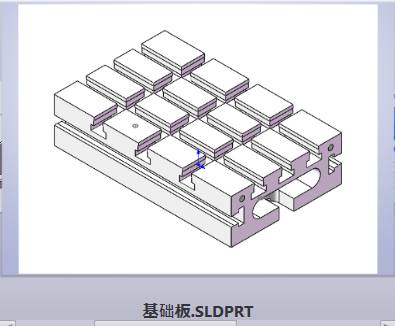
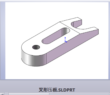
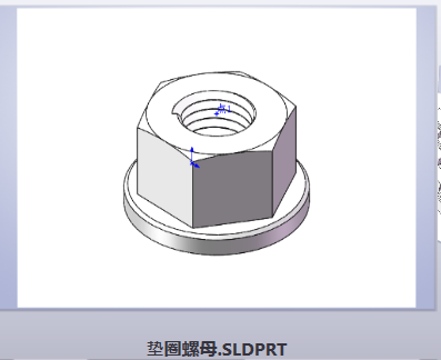
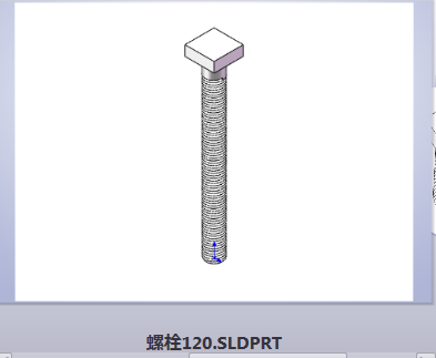
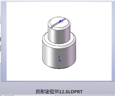
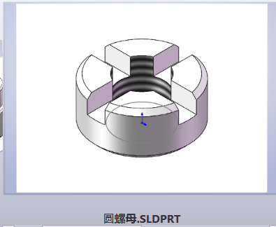
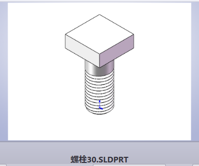
相关图片展示: