重型载货汽车9档双中间轴变速器设计外文翻译资料
2022-09-14 19:17:43
The fundamentals of power train design constitute the central element of this chapter and serve as the basis for the methodological competence and system competence for vehicle transmissions. The chapter starts with a discussion of the forces on the vehicle and the composition of the traction demand. This is juxtaposed with the provision of torque of the power train. The relationship of these two factors, demand and traction force, will be shown for the case of driving at constant velocity, as well as for acceleration processes in Sects. 1.1 and 1.2.
One of the principle objectives of power train development is to ensure good driving dynamics at optimal fuel consumption. This conflict of objectives, appealing agility with concurrent increase in efficiency will be dealt with in Sect. 1.3.
In this regard, not only the transmission with the engine alone, but all torque-trans-mitting elements extending to the wheel will be considered as a complete system power train. To this point in time, in the development of a power train, often it is still common practice that transmission and engine are developed separately and later joined together and adjusted to each other, even though having in some cases very different development objectives. For the engine, a majority of development time is expended in executing the calibration (quasi-) statically on the engine test bench, however the transmission must be dynamically calibrated in the overall system of the vehicle.
Fuel consumption, emission, and comfort requirements imposed on vehicles; newer transmission technologies; and hybrid technologies in particular, require additional in-teraction between transmission and engine. In this regard it is not just information and data that is exchanged; rather, active, reciprocal influence occurs based on the situation. In the future, development of the transmission and development of the engine will be much more closely interlinked in order to satisfy the overall requirements [30]. This guarantees optimal interplay of the strengths of the individual components, and thus increases the ef-ficiency of the complete vehicle (Fig. 1.1).
Fig. 1.1 Engine and trans-mission-common strength. In system and in detail
In Sect. 1.5 the criteria for selecting the right gear ratio are explained.
The task of the transmission and engine is to provide the necessary motive power for every driving situation. This applies for constant driving, acceleration, and deceleration. Simultaneously, high levels of comfort, good dynamic characteristics, and low fuel con-sumption, as well as low emissions, are demanded. What this means for the design of the power train is the object of this chapter.
1.1emsp; Traction Demand and Torque Supply at Constant Speed
To accelerate a vehicle, decelerate a vehicle, but also to drive at constant velocity means overcoming resistances. The calculation of these driving resistance forces that are regu-lated on a situation-dependent basis, as well as the required motive power, and the forces between vehicle and road surface, or on the component interfaces is the task of the driving performance calculation, and it is one of the cornerstones of power train design.
1.1.1emsp; Traction Demand at Constant Speed
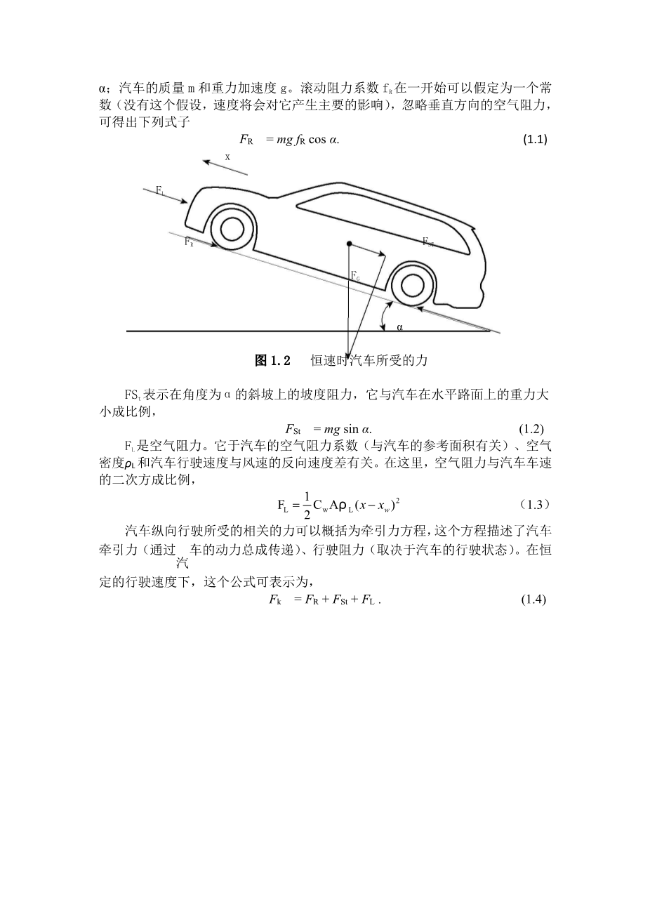
Various forces act on a motor vehicle; these forces are induced through aerodynamics, tire rolling resistance, friction in power train and chassis, gravity, and inertia. Figure 1.2 shows a vehicle on an inclined plane (uphill drive) with the acting forces.
FR designates the rolling resistance force, which is calculated by the use of the rolling resistance coefficient fR. The equation takes into account the slope angle alpha;; the vehicle mass m as well as gravity acceleration g are additional factors. The rolling resistance coefficient fR can be assumed as constant in an initial approximation—without this assumption the
dependency on velocity would be dominant—so that by ignoring the vertical aerodynamic forces the following relationship occurs
FR = mg fR cos alpha;. (1.1)
FSt represents the slope resistance force on a slope with the angle alpha;. It corresponds to the proportion of force component of the gravitation of the vehicle acting parallel to the road surface,
FSt = mg sin alpha;. (1.2)
FL is the air drag force. This depends on aerodynamic parameters of the vehicle (cW-value and reference area A), as well as air mass density rho;L and the velocity that arise from the difference of driving velocity x and wind speed xW acting against the direction of travel. In this regard, the air drag resistance force increases as a quadratic function of the velocity,
|
|
FL |
|
1 |
cW Arho; L ( x |
minus; xW )2 . |
(1.3) |
|
|
2 |
|||||||
The forces relevant for longitudinal vehicle movement can be summarized in the so-called traction force equation. This equation describes the balance between traction force Fk, which is made available through the power train of the vehicle, and the driving resistance forces, that act depending on the driving
剩余内容已隐藏,支付完成后下载完整资料
英语原文共 11 页,剩余内容已隐藏,支付完成后下载完整资料
资料编号:[148097],资料为PDF文档或Word文档,PDF文档可免费转换为Word


