5X33m连续梁桥设计与计算毕业论文
2020-04-23 20:11:20
摘 要
本设计根据任务书要求,结合《公路桥涵设计通用规范》和《钢筋混凝土和预应力混凝土桥涵设计规范》的要求,对5×33m预应力连续梁桥进行设计与计算。采用了Madis Civil 桥梁软件,进行了辅助计算。其中有温度荷载、移动荷载、支座沉降、施工阶段分析、查看分析结果等。
本设计主要是预应力混凝土梁的上部结构的设计与计算,其中主要进行了桥梁尺寸的拟定、荷载内力计算、预应力钢束的布置与估算、预应力损失及有效应力计算、抗裂验算、持久状况应力计算和短暂状况构件的应力计算。
最后,经过一系列的验算,表明本设计的预应力混凝土桥梁桥满足设计规范的要求。
关键字:连续梁桥;预应力;设计;验算
Abstract
According to the requirements of the task book, combined with the requirements of "General Code for Design of Highway Bridges and Culverts" and "Code for Design of Reinforced Concrete and Prestressed Concrete Bridges and Culverts", the design and calculation of 5 *33m Prestressed Continuous Girder Bridge are carried out. Madis civil bridge software is used to carry out the auxiliary calculation. Thermal load, moving load, bearing settlement, analysis of construction stage and analysis results are included.
This design is mainly about the design and calculation of the superstructure of the pre-stressed concrete beam. It mainly includes the formulation of bridge size, the calculation of load internal force, the layout and estimation of the pre-stressed steel bundles, the calculation of prestress loss and effective force, the checking calculation of crack resistance, the calculation of stress in the durable state and the stress calculation of components in the transient state.
Finally, through a series of checking calculation, it shows that the design of the pre-stressed concrete bridge meets the requirements of the design specifications.
Key words: continuous girder bridge; prestress; design; check calculation
目 录
摘要 I
Abstract II
第一章 设计说明 1
1.1技术指标 1
1.2材料 1
1.2.1混凝土 1
1.2.2钢材 1
1.3设计规范 1
第二章 方案设计 3
2.1桥型布置 3
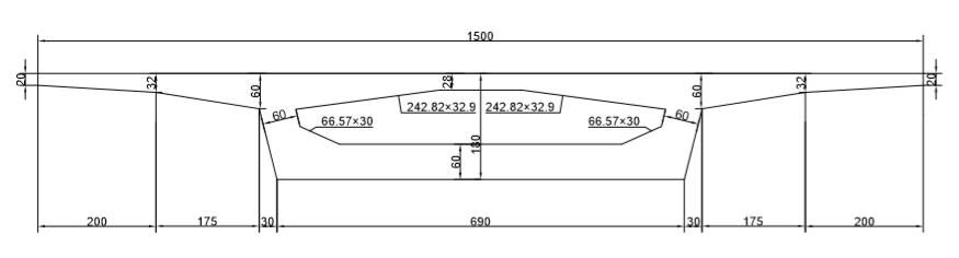
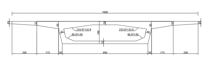
2.2截面尺寸拟定 3
2.1梁高 3
2.2横截面 3
第三章 作用效应计算与作用效应组合 5
3.1恒载计算 5
3.1.1一期恒载——自重 5
3.1.2二期恒载——桥面铺装和栏杆 7
3.2活载荷载作用效应计算 8
3.2.1汽车冲击系数 8
3.2.2箱梁的横向分布系数 9
3.2.3汽车荷载效应计算 9
3.3温度应力内力计算 12
3.3.1年平均温差 12
3.3.2温度梯度 15
3.4支座沉降计算 18
3.5荷载组合 20
3.5.1按承载能力极限状态设计 20
3.5.2按正常使用极限状态设计 21
3.5.3计算结果 22
第四章 预应力钢束估算及布置 25
4.1预应力钢束的估算 25
4.2预应力钢筋估算结果 25
4.3预应力钢束布置原则 27
4.4刚束布置 28
第五章 预应力损失及有效预应力计算 31
5.1钢筋预应力损失估算 31
5.1.1预应力钢筋与管道间摩擦引起的预应力损失 31
5.1.2锚具变形、钢筋回缩和接缝压缩引起的应力损失 32
5.1.3预应力钢筋分批张拉时混凝土弹性压缩引起的应力损失 32
5.1.4钢筋松弛引起的应力损失 33
5.1.5混凝土收缩、徐变引起的应力损失 33
5.2钢筋的有效预应力计算 34
第六章 截面强度计算 37
6.1正截面强度验算 37
6.2斜截面抗剪验算 40
6.2.1斜截面内混凝土和箍筋共同抗剪承载力 40
6.2.2预应力弯起钢筋的抗剪承载力 41
第七章 抗裂验算 43
7.1正截面抗裂验算 43
7. 2斜截面抗裂验算 45
第八章 持久状况应力计算 47
8.1正截面混凝土法向压应力验算 47
8.2正截面受拉区钢筋拉应力验算 47
8.3斜截面混凝土的主压应力验算 48
第九章 短暂状况构件应力验算结果 49
9.1 短暂状况构件应力验算 49
参考文献 50
致谢 51
第一章 设计说明
1.1技术指标
(1)荷载等级:公路I级
(2)桥面宽度:0.5m(防撞护栏)×2 3.5m(行车道)×4=15m
(3)桥面铺装:10cm沥青混凝土 6cm混凝土调平层
(4)桥面横坡:1.5%
(5)设计使用年限:设计基础期100年
1.2材料
1.2.1混凝土
预应力混凝土箱梁 C50混凝土
防撞护栏 C30混凝土
桥面铺装 沥青混凝土
1.2.2钢材
(1)预应力钢筋
所用预应力筋均采用高强低松弛钢绞线。单根钢绞线公称直径为Φs15.2mm,标准强度,弹性模量。
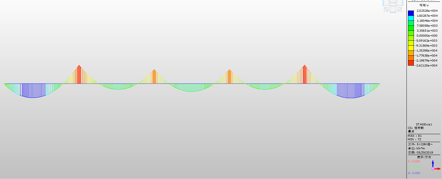
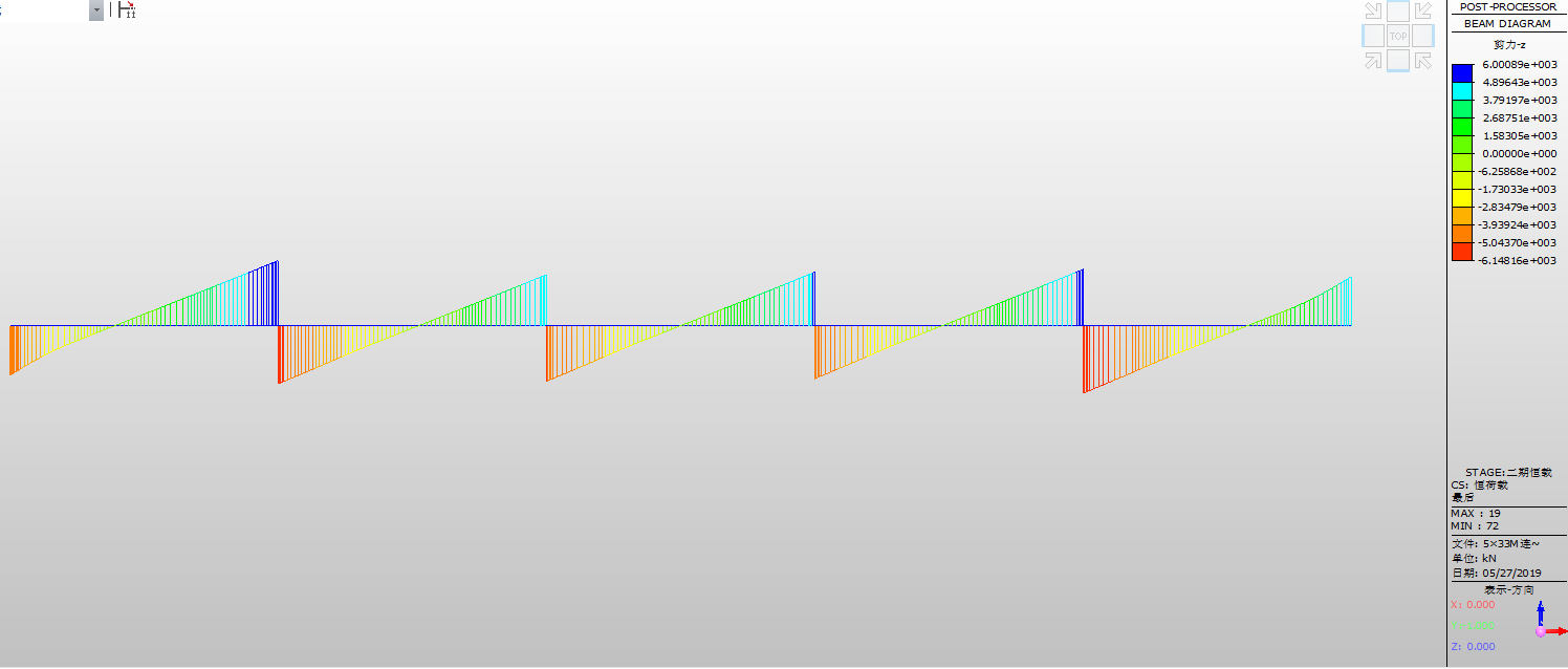
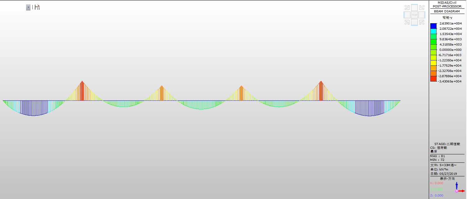
相关图片展示: