350客位双体客船型线设计及阻力性能数值计算毕业论文
2020-02-18 00:31:06
摘 要
双体船与常规的单体船相比具有明显的优点,包括具有良好的稳性、操纵性、快速性、耐波性,抗沉性等性能,以及甲板面积大、上层建筑发达等,在国际船舶业得到了广泛的运用。因此,研究双体船的设计方法和水动力性能,可以为双体船的设计提供指导,具有实用意义和广阔的应用前景。
本文设计了一艘航行于沿海遮蔽航区的350客位双体旅游客船,完成了主尺度确定和型线设计工作,利用CFD软件STAR-CCM 计算了设计船不同片体间距船长比的阻力性能,分析了设计船不同间距船长比对阻力性能的影响,得到了设计船合适的片体间距。具体内容如下:
(1)主尺度确定方面,本文主要从布置地位出发,参考母型船资料和规范要求,初步确定了设计船的主尺度。然后进行浮性、稳性、快速性的校核工作,验证了主尺度等要素满足设计要求。
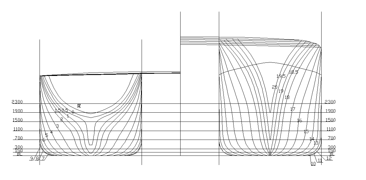
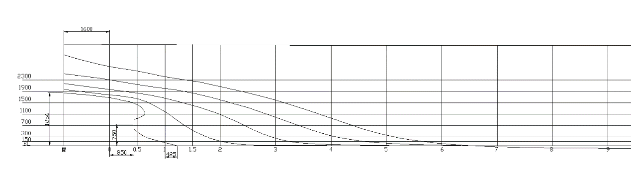
(2)型线设计方面,本文主要运用母型船改造法,根据母型船型线图先确定设计船横剖面曲线图,改造得到设计船的型线图。然后利用Rhino软件,根据设计船型线图进行三维建模,再利用Maxsurf软件进行静水力计算和稳性计算,得到了设计船静水力曲线图、邦戎曲线、稳性插值曲线等。
(3)阻力计算方面,本文首先利用CFD软件STAR-CCM 计算了一条与设计船片体相近的Wigley船模的阻力性能,将计算结果与模型试验结果对比,验证了数值方法的合理性。完成数值方法验证工作后,利用STAR-CCM 计算了设计船的总阻力系数,得出设计船不同片体间距对阻力性能的影响规律,得到了设计船合适的片体间距。
本文完成了350客位双体旅游客船的主尺度确定、型线设计工作,得到了设计船的主要要素、型线图、静水力曲线图等设计成果。并通过阻力计算工作,发现在设计航速下,片体的有利干扰发生在间距船长比为0.2的情况下,此时设计船所受到的总阻力最小。验证了在主尺度确定阶段得到的片体间距既能满足布置地位的要求,也能使船体所受阻力较小,满足快速性要求。
关键词:主尺度确定;型线设计;CFD;阻力计算;片体间距
Abstract
Compared with conventional single-hull ships, catamaran has obvious advantages, including good stability, maneuverability, rapidity, seakeeping ability, anti-sinking ability, large deck area and developed superstructure, which are widely used in the international shipping industry. Therefore, the research on the design method and hydrodynamic performance of catamaran can provide guidance for the design of catamaran, which has practical significance and broad application prospect.
This paper design a ship sailing in the coastal shelter area of the 350 seat passenger catamaran tourism, completed the principal dimensions determine and profile design work, CFD software STAR-CCM was used to calculate the resistance performance of the designed ship with different span length ratios, analyzed the design ship captain different spacing ratio on the resistance performance, and the proper body spacing is obtained. The specific contents are as follows:
(1) in terms of the determination of the main dimensions, this paper initially determined the main dimensions of the designed ship from the perspective of layout status and referring to the data and specification requirements of the mother ship. Then, the floating, stability and rapidity are checked to verify that the main scale and other elements meet the design requirements.
(2) in terms of profile design, this paper mainly uses the method of transformation of mother-type ship. Based on the mother-type ship profile diagram, the transverse section diagram of the designed ship is determined first, and the profile diagram of the designed ship is obtained through transformation. Then, Rhino software is used to carry out three-dimensional modeling according to the designed ship line drawing, and Maxsurf software is used for hydrostatic calculation and stability calculation, so as to obtain hydrostatic curves, bonjung curves and stability interpolation curves of the designed ship.
(3) in terms of resistance calculation, this paper firstly used CFD software STAR-CCM to calculate the resistance performance of a Wigley ship model similar to the designed ship sheet, compared the calculated results with the model test results, and verified the rationality of the numerical method. After the verification of the numerical method, the STAR-CCM method was used to calculate the total resistance coefficient of the designed ship, and the law of the influence of different interbody spacing on the resistance performance of the designed ship was obtained, and the appropriate interbody spacing of the designed ship was obtained.
This paper completes the determination of the main dimensions and the design of the profile lines of the 350 passenger catamaran tourist ship, and obtains the design results of the main elements, shape lines and hydrostatic curves of the design ship. Through resistance calculation, it is found that at the design speed, the favorable interference of the pieces occurs when the spacing length ratio is 0.2, and the total resistance of the designed ship is the least. It is verified that the interbody spacing obtained in the determination stage of the main scale can not only meet the requirements of layout status, but also make the hull subjected to less resistance and meet the requirements of rapidity.
Key Words: Determination of main scale; Profile design; CFD; Resistance calculation; Strip spacing
目录
摘 要.............................................................................................................................................Ⅰ
Abstrct.........................................................................................................................................II
第1章 绪论 1
1.1 研究背景及意义 1
1.2 国内外研究现状 2
1.2.1 双体船设计 2
1.2.2双体船阻力性能计算 3
1.3 本文的主要工作 4
第2章 主尺度确定及性能校核 5
2.1 主尺度初选思路 5
2.1.1主尺度确定流程 5
2.1.2设计任务分析 6
2.1.3设计矛盾分析 6
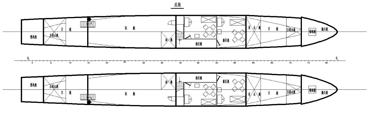
2.2设计船的布置特点 7
2.2.1主甲板 7
2.2.2二层甲板 9
2.2.3底舱 9
2.3主尺度初步确定 10
2.3.1船长L的确定 10
2.3.2船宽B的确定 11
2.3.3 片体长宽比L/b的确定 12
2.3.4 片体间距比k/b的确定 12
2.3.5 吃水d和片体宽度吃水比b/d的确定 13
2.3.6 型深D的确定 13
2.3.7 片体方形系数Cb的确定 13
2.4浮性校核 14
2.4.1 设计船排水量 14
2.4.2 设计船总重量 15
2.4.3 浮力平衡 18
2.5稳性校核 19
2.5.1 初稳性高 19
2.5.2 横摇周期 20
2.6快速性校核 21
2.7设计船主要要素 21
第3章 型线设计及静水力计算 22
3.1型线设计流程 22
3.2型线要素的确定 23
3.2.1 设计船棱形系数Cp的确定 23
3.2.2 设计船浮心纵向位置Xb的确定 23
3.2.3 设计船平行中体长度Lp和位置的确定 24
3.2.4 水线面系数Cw的确定 24
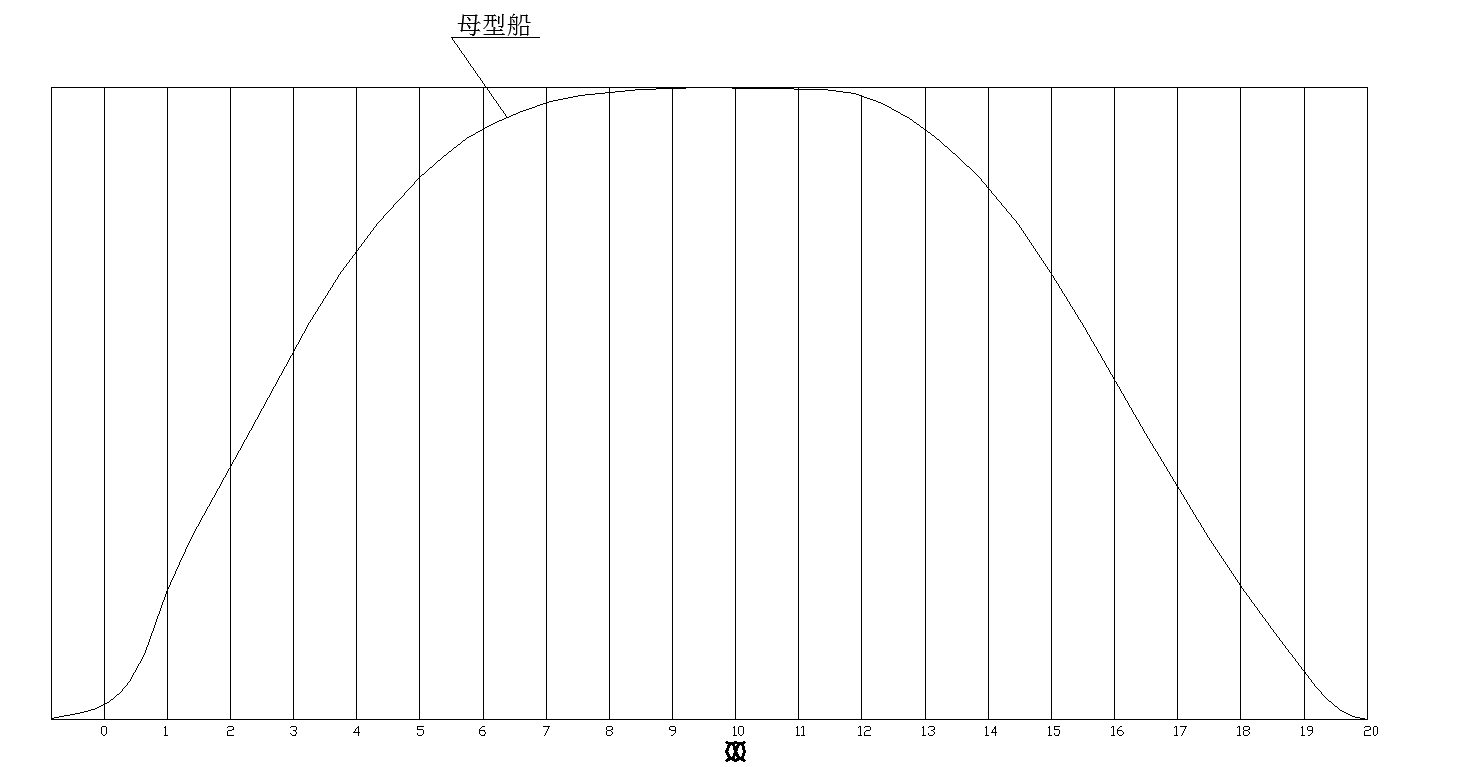
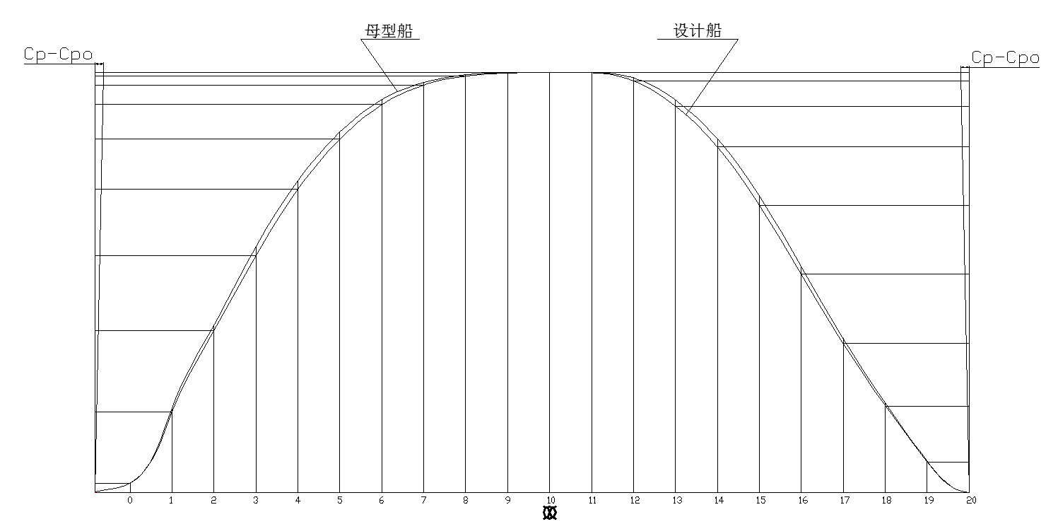
3.3 修改横剖面面积曲线 24
3.3.1 修改Cp 24
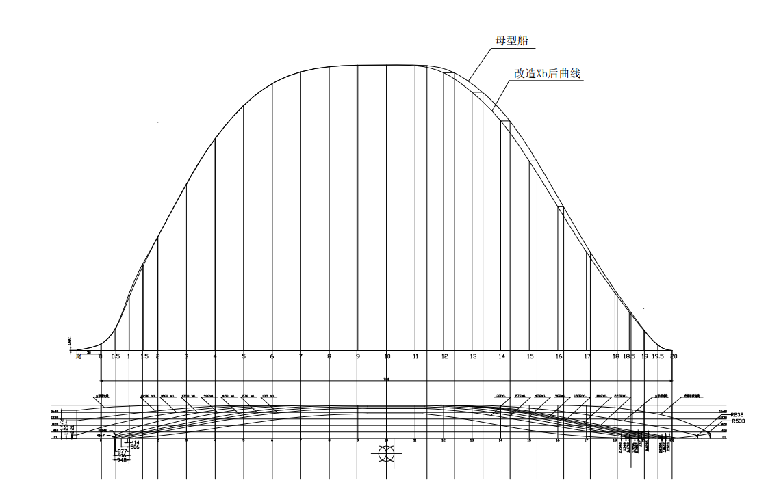
2.3.2 改造Xb 25
3.4 绘制设计船型线图 26
3.4.1 改造半宽水线图 27
3.4.2 绘制横剖线图、纵剖线图和半宽水线图 27
3.5 三维建模 30
3.5.1 从型线图中导入数据 30
3.5.2 生成曲线 30
3.5.3 建立船壳面 31
3.5.4 建立双体船模型 31
3.6 静水力计算 32
3.6.1计算过程 32
3.6.2绘制静水力曲线 34
3.7 绘制设计船邦戎曲线 35
3.8 绘制稳性插值曲线 36
第4章 阻力计算 37
4.1 验证CFD数值方法 37
4.1.1 Wigley模型 37
4.1.2 数学模型 39
4.1.3网格数研究 40
4.1.4边界层研究 42
4.1.5前处理 43
4.1.6数值计算 45
4.2设计船阻力计算 46
4.2.1收敛分析 46
4.2.2间距船长比对片体阻力的影响 47
4.3波形分析 47
第5章 总结与展望 50
5.1总结 50
5.2展望 50
参考文献 51
附录1.............................................................................................................................................53
致谢 54
第1章 绪论
1.1 研究背景及意义
二十一世纪是海洋的世纪,探索和利用海洋是世界今后的发展趋势。而船舶作为国防工业的重要装备以及海上的交通工具,在探索和利用海洋的过程中将发挥重要作用。船舶作为一种建造成本高、使用周期长的产品,其成本的70%~80%决定于设计阶段[1],如何减少设计成本、提高使用周期,改善经济性是设计者要重点考虑的问题。
船舶设计是一项周期长,内容繁复,需要循序渐进、反复优化的工作。如果设计者能在船舶设计阶段对船舶的水动力性能尤其是船舶阻力性能进行预报,便能够在设计阶段对船体尺寸和结构进行优化改进,从而获得性能优良的船体。这样,不仅可以缩短船舶设计周期,也能够减少船舶实验次数,提高设计效率,减少设计成本。传统的船舶水动力性能预报方法是进行模型实验,该方法虽然能够较为准确的预报水动力性能,但存在许多缺点。如成本高、周期长、流场信息获取不全、存在尺度效应等等。因此在船舶设计过程,如果能有效果更好的方法来预报船舶水动力性能,对提高设计质量具有重要意义。
随着计算机技术和数值计算技术的飞速发展,通过计算机仿真模拟来预报船舶的水动力性能逐步得到推广应用,计算流体力学(CFD)也得到充分的发展。ANSYS FLUENT、OpenFOAM、STAR-CCM 等一系列商业化CFD软件的开发与应用使得数值模拟成为当今船舶水动力性能预报的主要方法,已在船舶自行设计中得到广泛的应用。CFD数值方法相比于模型实验,其成本低,速度快,不受模型、水池等硬件条件的限制,无尺度效应,可以得到详细充分的流场信息,便于分析船舶水动力性能等优点,已被大多数学者认可和采用。
船舶有着许多不同的船型,从是否具有片体和片体的数量可以把船舶分为单体船、双体船和多体船等。长期以来,船舶基本为单体船,随着建造工艺和技术水平的提升,双体船和多体船在近一个世纪逐渐发展起来,开发出了小水线面双体船、穿浪双体船等船型,均具有优异的性能,得到了较为广泛的应用。随着人们生活水平的提高和旅游业的蓬勃发展,水上旅游越来越受到人们的追捧。而双体船不管是作为旅游客船还是作为商务船,凭借着其优异的性能,都越来越受到船东和消费者的青睐。
设计船为双体客船,其船型的设计关键在于其水动力性能的研究,而阻力性能的预报是水动力性能研究的重要内容。因此,本文也采用数值模拟CFD方法计算船舶阻力。
1.2 国内外研究现状
1.2.1 双体船设计
双体船是一种高性能排水型船,它由两个相同的片体和一个连接桥所组成,双体船与常规的单体船相比具有明显的性能优势,甲板面积大、兴波小、稳性好、操纵性好、横摇周期短、抗沉性等[2],所以双体船一直都是被研究的热点。
国内双体船市场现状介绍如下。2011年,珠海江龙船舶制造有限公司与天津某旅游公司签订21.6m双体客船建造合同,型长21.60m,型宽5.55m,型深2.18m,航速15kn,乘客96人。2012年,英辉南方造船有限公司与深圳市鹏星船务有限公司签订了建造两艘40m铝合金高速双体客船的合同,船长40.0m、总宽9.3m、型深3.4m、设计吃水1.2m,载客199人,设计航速31.5kn。2016年,武船集团为七一五所建造的国内最大双体船“瑞利10号” 海上综合试验平台在双柳基地顺利下水,船长82m,型宽32m,建成后将满足有关海上科研试验需求。2018年,江龙船艇与珠海永航运输有限公司签订32m双体旅游客船建造合同。次日,该公司又与台山川航船务有限公司成功签约198客位双体高速客船订单。32m双体旅游客船总长32.15m,型宽7.6m,设计航速14.5kn,乘客116人。该船采用钢铝复合结构,双机、双桨推进。198客位双体高速客船总长29.65m,型宽7.6m,最大航速19kn,乘客198人。现如今往返运营香港-澳门航线的高速双体客船最高速度可以达到42kn,载客400多人,长47.5m,宽11-12m,吃水1.8m,排水量700t。
国外双体船市场现状介绍如下。2013年,Gladding-Hearn造船厂为波士顿海湾国家邮轮公司建造的1艘150客位高速双体客船交付,船长98ft,船宽29.5ft,最高航速为30kn。2017年,Metal Shark美国造船厂向Entertainment Cruises下属Potomac Riverboat公司交付了2艘高速铝制双体客船,船长88ft,设计可运输149名乘客;同年9月份,Metal Shark造船厂还被客船运营商Hornblower公司选中,建造5艘高速铝制双体船,包括4艘长97ft、载客350人客船和1艘长85ft、载客150人的客船。也是在2017年,Incat Crowther公司为船东Majestic渡船公司建造了3艘船长39m,船宽10m的双体运营客船。该系列船具有节能高效、性能优异的特点,已经逐渐建造完成并投入使用。2018年,英国Wight船厂向苏格兰旅游运营商The Loch Ness by Jacobite公司交付了一艘双体客船,船长21.34m,船宽7.6m,载客200人。该船外形设计能提供低重量的船体结构,具有全生命周期的效率和更低的燃料消耗。
通过简单介绍上述近几年国内外的双体船,尤其是双体客船的建造和投入运营的情况,可以发现双体船凭借自身的优异性能,已经越来越被人们所接受认可。在当今仍不景气的船舶市场下,双体船有着很好的发展前景。
1.2.2双体船阻力性能计算
由于CFD数值方法相比于模型实验具有诸多优点,目前已广泛运用于双体船阻力性能计算。国内外学者近五年的研究如下:
以上是毕业论文大纲或资料介绍,该课题完整毕业论文、开题报告、任务书、程序设计、图纸设计等资料请添加微信获取,微信号:bysjorg。
相关图片展示: